Steam Turbine: Difference between revisions
| Line 94: | Line 94: | ||
<sub>[[Image:Models-Steam-Turbine-image004.gif]]</sub> | <sub>[[Image:Models-Steam-Turbine-image004.gif]]</sub> | ||
<math>\mathbf{\ | <math>\mathbf{\mathit{Work=Enthalpy_{in}-Enthalpy_{out}}}</math> | ||
The analysis of turbine performance starts with the ideal turbine. The ideal work is what a turbine could produce when expanding steam from given initial conditions to a given final pressure with 100% efficiency. Thus step 1 of the calculation is: | The analysis of turbine performance starts with the ideal turbine. The ideal work is what a turbine could produce when expanding steam from given initial conditions to a given final pressure with 100% efficiency. Thus step 1 of the calculation is: | ||
Revision as of 04:34, 20 July 2007
Navigation: Main Page -> Models -> Energy Transfer Models
General Description
The steam turbine converts steam energy into shaft work, which then can be converted to electrical work through the generator.
When modelling the steam turbine, the steam inlet condition needs to be specified, this includes the Temperature, pressure, mass flow and quality of steam. This information is specified in the Steam Feeder.
The configuration of the Steam turbine is very simple; the user needs only supply the required exhaust pressure and the Turbine isentropic efficiency.
From the information provided, SysCAD will calculate the exhaust steam temperature, quality and the amount of power that can be generated from the steam.
Diagram
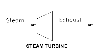
The diagram shows the default drawing of the Steam Turbine, with the required connecting streams. The Steam Turbine expects the inlet to be Steam, the valid conditions are: 2 phase saturated wet steam, pure saturated steam or superheated steam. The outlet from the turbine is the Exhaust steam and generated power.
Inputs and Outputs
|
Label |
Input / Output |
No. of Connections |
Description | |
|
|
|
Min |
Max. |
|
|
Steam |
In |
1 |
1 |
The steam inlet. |
|
Exhaust |
Out |
1 |
1 |
The exhaust steam. |
Model theory
From the first law of thermodynamics, the energy balance is obtained by:
File:Models-Steam-Turbine-image002.gif
[math]\displaystyle{ \mathbf{\mathit{\boldsymbol{\Delta}E=-\boldsymbol{\Delta}[(H+K+P)m]+Q-W}} }[/math]
Assumptions
1) The process is in steady state, thus dE = 0.
2) A turbine can have heat transfer out through the casing, but typically they are well insulated so that the heat loss is small and given that the mass flow rate is large, the heat transfer per unit mass is almost nothing and thus is ignored. Thus Q = 0.
3) The height difference between the inlet and outlet is negligible in terms of potential energy and this term is ignored. Thus, P = 0
4) There may be some velocity effects (kinetic energy) if the exit velocity is very high. This is usually not known or measured and is implicitly included in the turbine efficiency - this term is ignored. Thus, K = 0.
5) There is no loss of mass. Thus, mass in = mass out.
Calculating Work
From the above assumptions, the simplified energy balance is:
File:Models-Steam-Turbine-image004.gif
[math]\displaystyle{ \mathbf{\mathit{Work=Enthalpy_{in}-Enthalpy_{out}}} }[/math]
The analysis of turbine performance starts with the ideal turbine. The ideal work is what a turbine could produce when expanding steam from given initial conditions to a given final pressure with 100% efficiency. Thus step 1 of the calculation is:
(1) Calculate the ideal work output - an ideal turbine is isentropic so that exit entropy equals inlet entropy - the exit steam conditions and work is obtained from this.
The actual work is determined from the turbine efficiency (also known as the isentropic or adiabatic efficiency), which is simply a measure of how well the turbine is doing compared to a perfect machine operating under the same conditions. Thus step 2 of the calculation is:
(2) Actual work = ideal work * turbine efficiency.
The actual enthalpy out can be calculated from the actual work done, such step 3 is:
(3) Actual enthalpy out = enthalpy in - Actual work
From the actual enthalpy out and the specified required pressure of the exhaust, the actual temperature out and the quality of the steam can be calculated.
Calculating Power
Power = Actual work * mass flow * Generator Efficiency (MechEfficiency)
Checking of Steam conditions
During the work calculations, checking of steam quality is important since the exhaust may have some condensation in it if enough energy is extracted from it. (Generally this is never more than a few percent in real turbines because water droplets moving close to the speed of sound can have a terrible erosive power which can damage the last few blade rows very quickly).
Typically, there are four cases of steam conditions that can exist in the turbine calculation:
|
CASE |
INLET STEAM |
IDEAL EXHAUST |
ACTUAL EXHAUST |
|
(1) |
superheated |
superheated |
Superheated |
|
(2) |
superheated |
saturated |
Superheated |
|
(3) |
superheated |
saturated |
Saturated |
|
(4) |
saturated |
saturated |
Saturated |
NB: saturated inlet means saturated exhaust.
In the case where the steam has some condensate in it - i.e. wet steam or the quality (x) is less than 100%, the calculations gets slightly lengthier.
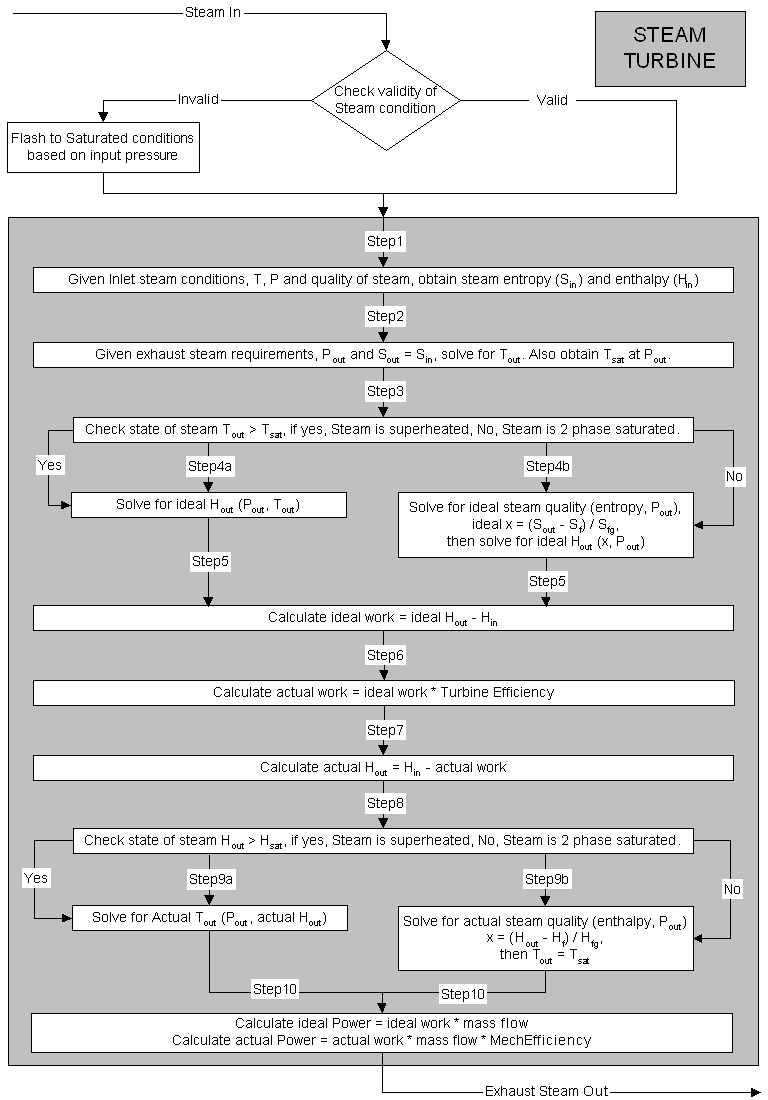
For a detailed step-by-step calculation routine, please see section under Flowchart.
Flowchart
The following shows the steps in determining quality and condition of the exhaust steam, as well as the calculation of power generated.
Data Sections
The default access window consists of two sections,
a) The first tab has the same name as the model tag, contains general information relating to the unit.
b) The last section Audit contains summary information required for Mass and Energy balance. See Model Examples for enthalpy calculation Examples.
First Section- Tag Name
|
Tag / Symbol |
Input / Calc |
Description |
|
| ||
|
Requirements | ||
|
On |
Tick Box |
If this option is switched off, then the turbine will behave like a pipe model. Thus, inlet conditions = outlet conditions. |
|
P_Rqd |
Input |
The required exhaust steam pressure. |
|
Efficiency |
Input |
The required isentropic or adiabatic turbine efficiency. |
|
MechEfficiency |
Input |
The required efficiency of the power generator. |
|
TrackSteamFd |
Tick Box |
If this option is selected, then the feed steam quality will be checked. If the steam quality is less that that specified in the TrackSteamFrac field, a warning NOTE will be given in the condition field in the current access window. |
|
TrackSteamFrac |
Input |
The minimum steam fraction expected in the feed stream. See above. |
|
Results | ||
|
Qm |
Calc |
The mass flow of steam |
|
Ti |
Calc |
The inlet steam temperature. |
|
To |
Calc |
The exhaust steam temperature. |
|
Pi |
Calc |
The inlet steam Pressure. |
|
Po |
Calc |
The exhaust steam Pressure. |
|
Vfi |
Calc |
The inlet steam quality (vapour fraction). |
|
Vfo |
Calc |
The exhaust steam quality (vapour fraction). |
|
SatT |
Calc |
The exhaust steam saturation temperature (at Pressure). |
|
SatP |
Calc |
The exhaust steam saturation pressure (at temperature). |
|
Sgi |
Calc |
The inlet steam entropy. |
|
Sli |
Calc |
The inlet water entropy. |
|
IdealWork |
Calc |
The ideal work = ideal enthalpy of exhaust - enthalpy of inlet steam. |
|
TurbineWork |
Calc |
The Turbine work = ideal work * turbine efficiency. |
|
Work |
Calc |
The actual work = Turbine work * MechEfficiency |
|
IdealPower |
Calc |
The ideal power = ideal work * mass flow. |
|
TurbinePower |
Calc |
The Turbine Power = ideal power * turbine efficiency. |
|
Power |
Calc |
The actual power = Turbine Power * MechEfficiency. |
|
H2O_Frac |
Calc |
The stream steam/water fraction. Thus, has the stream any impurities. |
|
ExhaustMode |
Display |
The exhaust steam quality, valid options are: Superheated, two phases saturated or off (when turbine is switched off). |
Hints and Comments
1) The steam turbine has a single extraction pressure, for modelling work of turbines with multiple extraction pressure sections; a number of turbines can be drawn in parallel with a steam feed splitter to simulate the process.
2) Always double check if the steam feed conditions is valid. Try to use the VLE option in the Feeder-Cross Page Connector to add in a level of checking.
3) If steam feed is not valid, then SysCAD will try and flash the feed stream to its saturated conditions (based on the inlet pressure.) This will change the feed stream temperature, as the flashing of the mixture will cool down the stream, while trying to keep its enthalpy constant.

