TCE Functionality Overview
Navigation: Models ➔ TCE Models ➔ Thermodynamic Calculation Engines ➔ TCE Functionality Overview
| Thermodynamic Calculation Engines (TCEs) | TCE Options | TCE FAQ | |||||
|---|---|---|---|---|---|---|---|
| TCE Functionality Overview | TCE Species Mapping | TCE Configuration Options | AQSol | ChemApp | PHREEQC | OLI | |
Latest SysCAD Version: 25 October 2024 - SysCAD 9.3 Build 139.36522
Workflow - Using TCE Add-Ons in a SysCAD Model
To utilise these add-ons in a model, it is necessary to place at least one Model Configuration unit onto the flowsheet and perform the configuration. Multiple model configurations can be employed if needed. Subsequently, unit models that utilise these configurations are added. These unit models can be directly integrated into the process model. Examples of such unit models include reactors, evaporators, flash tanks, reverse osmosis units, and so forth. Alternatively, these unit models can be used to calculate the equilibrium compositions of streams without affecting the model, serving as side calculations. Additionally, there is a direct calculation unit operation available. This operation enables the direct testing of the model for specific situations, which is analogous to using the software directly for single point calculations.
To summarise, the use of these models in a flowsheet involves the following steps:
- Add in a TCE Model configuration (TMC): This must be added to the flowsheet before any other TCE unit operation. Its main uses include:
- Selecting the TCE database file to use with the specific thermodynamic software.
- Performing mapping between species in the SysCAD database (syscad.93.db3) and species within the thermodynamic software and database file.
- If required, modifying how the model is used within the process model, such as adjusting how solids and gases are formed to account for supersaturation.
- Adding other SysCAD unit operations (TCE and non-TCE):
- Dropping unit operations onto the flowsheet.
- For TCE unit operations, selecting the TCE model configuration (TMC) to use for the thermodynamic calculations.
- Setting parameters for the thermodynamic calculation specific to the TCE being used and the unit operation being simulated.
- Adding required species for mapping:
- The use of thermodynamic software often results in the generation of species which are not in the project. Users need to add additional species to the project database from either the SysCAD default database, from hardwired species, or from other data sources. SysCAD provides clear messages and useful functionality to guide the user in adding the required species.
- For aqueous species, these may be in the form of neutral species or ions. There is functionality in place within SysCAD to automatically determine how ions are used to build SysCAD species. Ionic species do not require full thermodynamic information as they are used as intermediates in the building of SysCAD species. The SysCAD species are apparent species, and the ions are true chemical speciation predicted by the thermodynamic software.
Leveraging Multiple TCE Packages in a Single Project
Multiple types of TCE software can be loaded in a single SysCAD project. For example, in a sulfide mineral smelting plant with an acid plant and flue gas scrubbers, one could:
- Use ChemApp to model the smelting operations.
- Use OLI to model off-gas scrubbing and the metallurgical acid plant.
- Use AQSol and/or PHREEQC to model the treatment of wastewater.
Each of these software packages has its strengths, and the flexible SysCAD architecture allows for the use of each of them as appropriate, alongside standard SysCAD unit operations.
Parallel processing is incorporated as appropriate in a process flowsheet. Thus, multiple TCE calculations can be performed in parallel while a SysCAD process model is solving.
A Simplified Guide to TCE Architecture and its Components
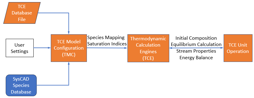
A simplified illustration of the interaction between a TCE model configuration, an engine, and a unit operation is shown in the figure below.

- The TCE database file is loaded into the TCE model configuration.
- The TCE model configuration handles species mapping between the TCE database file and the SysCAD Species database.
- User settings: which consist of convergence tolerances, saturation indices, exclusion of solids, etc., are provided to the TCE model configuration.
- This is then used by the Thermodynamic Calculation Engine when it receives a task from a TCE unit operation.
- The task from the TCE unit operation will specify which TCE model configuration to use.
SysCAD TCE Models User Functionality
When a TCE-enabled unit is placed on a SysCAD sheet and linked to a model configuration, it provides much more than just a calculation node in your process model. A number of analysis and reporting features are embedded within each unit, including:
- parametric sweeps: The user can generate plots of chemical speciation, enthalpy, pH, and many other parameters as a function of temperature. For side calculations, the effect of adding or removing a species can also be plotted.
- deportment: the deportment of elements between different phases can be viewed and exported to better understand what is occurring within a complex operation. Deportment calculations can be used as control parameters, i.e. calculate the lime addition required to precipitate 90% of magnesium sulfate from a stream.
- elemental balances: elemental balances are shown for both the TCE balance (i.e. the green control volume in the above figure), and the SysCAD balance (i.e. the black control volume in the above figure). This is an important tool for diagnosing mapping issues when developing a model.
- heat balances: a summary of the heat balance is shown for identifying heat sources and sinks. The overall heat requirements for the specific calculation done within a unit are clearly displayed.
- warning/error messages: clear warning and error messages specific to each unit are clearly displayed. Details and suggestions on how to fix the errors/warnings are written to the message log.