Project Window
Navigation: User Guide ➔ Windows ➔ Project Window
| Application Window | Message Window | Graphics Window | Access Window | Explorer Window | Trend Window | Controls Window | TagList Window | Project Window |
|---|
Latest SysCAD Version: 19 March 2024 - SysCAD 9.3 Build 139.35102
Introduction
The project structure is outlined in the Project Window.
To access the Project Window: Command Path: View - Project
The Project Window consists of five tab pages:
| Files | This is used to list all associated files for the current project. |
| Environment | This is used to list the Location of project files |
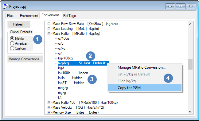
| Conversions | This is used to list all the engineering units available to the user. |
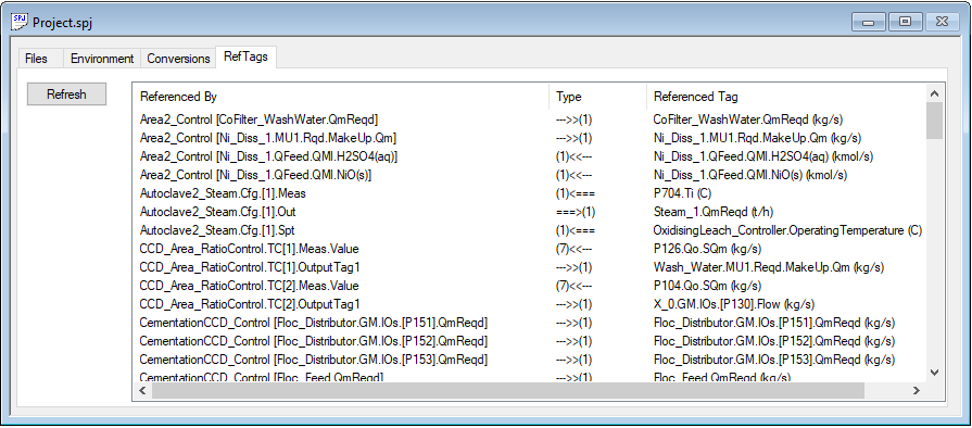
| RefTags | This is used to list all the variables referenced by the PID controllers or Pgm files. |
Notes:
- Caution: If you click on the X button on the top right hand corner of the dialog box, it is equivalent to the Close Project command, NOT the close dialog box. If you do not want to close the project, click on the cancel button when you are asked if you want to save the project.
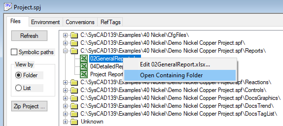
- In Build139, user can right click on any of the file path or document in the Files or Environment list to get the "Open Containing Folder" popup option, clicking on this will activate the "Windows File Explorer", showing the folder or file of interest. If the document can be edited, then "Edit xxxxx" will also be visible on the right click popup.
- For the models list, please use the Explore Window.
Files List
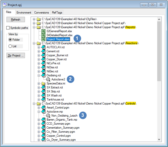
Click on the Files Tab will open up the list of files generated or used by SysCAD for the opened project. The files in this window are grouped together for easy reference. A typical example is as follows:
Models List
For the models list, please use the Explore Window.
Environment List
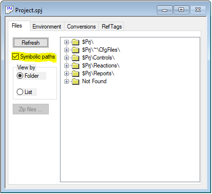
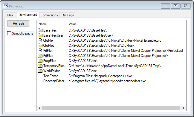
The environment page of the Project Window shows a list of relative path names used for folder/file paths.
Conversion List
|
The conversion units list displays all the Conversion types and units that are available in SysCAD. This list indicates the SI units and Default display units for each Conversion family. The Conversion family name is shown in square brackets next to the descriptive name. The conversion table is stored in ..\SysCADxxx\Basefiles\Default.93.db3. To add/modify the existing engineering units (excluding SI units), refer to Conversions Table for instructions. In the example screenshot:
Please see Conversions for more information on this topic. |
RefTags List
The RefTag list is for user information only, it builds and displays a list of all the reference tags used in the projects. These include any read/write (GET/SET) tags used by models (e.g. PID controller, PGM files - General controller).
NOTES:
- The list is built during the first iteration of a project solve or project run. Therefore, if the project has not yet been solved, the list will not appear. To display the list, after the project solve/run has been started, press on the refresh button on the following dialog box.
- In this example, we can read that P704.Ti is an input variable for the Autoclave2_Steam controller (measured value). The controller output then manipulates the Steam_1.QmReqd (the steam 1 mass flowrate required) variable.
- The referenced tags are also indicated by displayed coloured triangles on the relevant access window or Trend window, as described in Controlled and Referenced Variables.
