Precipitator3 Model Options
Navigation: Models ➔ Alumina Models ➔ Precipitator3 ➔ Model Options
| Precipitation3 | Model Theory - Growth | Model Theory - PSD | Model Options | Data Sections | Dynamic Mode | Batch Operations (Probal) |
|---|
Latest SysCAD Version: 19 March 2024 - SysCAD 9.3 Build 139.35102
Related Links: Alumina 3 Bayer Species Model
BatchMode
Please see separate section Batch Mode for more information.
Cooling
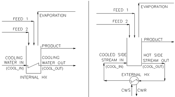
User can select from the following 3 Cooler options:
NOTES:
- The difference between the two cooling methods:
- With embedded cooling, an external coolant stream (usually water) is connected to and from the unit model.
- With external cooling, the stream takes liquor from, and returns it after cooling to the unit model.
- With both internal and external cooling the cooling connections must be connected to streams. The unit will not solve unless they are present. If a simplified cooling model is required, just use direct thermal loss via ThermalLossMethod
- The external cooling method determines the cooling load based on the outgoing and incoming temperature difference of the cooling stream. It then uses this cooling load to determine the thermal balance. The actual stream flow is ignored, i.e. it does not mix it with the tank contents.
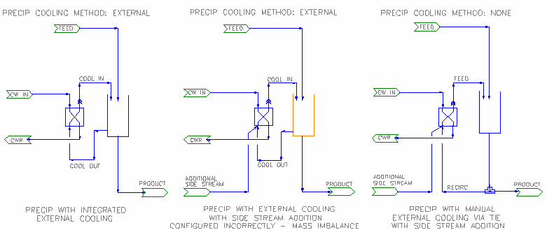
- External cooling allows you to use a separate specific exchanger model in the simple case of a single stream being returned directly to the tank so that you can get reporting information from the exchanger.
- If the recycle stream must be changed, say by mixing with cool liquor from another source, then you should take a side stream from a splitter on the outlet stream, cool this, then return this to the tank inlet along with any added liquid.
Reactions
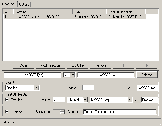
Arbitrary reactions may be included. For example to model oxalate coprecipitation:
- Oxalate chemistry is complicated - in pure synthetic liquors, oxalate solubility is of the order of 1gpl.
- The presence of other organic materials (in particular high molecular weight humic substances) can increase the solubility to 3-4gpl.
- This stabilizing effect is however variable and unpredictable.
- Rates and equilibria are best modelled based on actual plant data if this is available.
Note:
- Reactions are done after the precipitation calculations but before bypassed liquor is added.
- Reactions in the precipitator model may not include Heat Exchange section or Species Sources/Sinks. If these are included in the rct file a load error is given.
- Another reaction involving water would be carbonation from atmospheric CO2(g). The reaction 2NaOH(aq)+CO2 = Na2CO3(aq)+H2O(l) produces water, and consumes caustic; it would be best implemented in an overflow pipe.
Reactions involving water or key alumina species
Because the model handles the key species (H2O, NaAl[OH]4, Al[OH]3) specially, it is recommended you not include reactions with these species unless the quantities involved are minor since doing so may upset the overall water balance in the model and the results can be unpredictable.
- In particular, steam should not be added directly to a tank since the water (H2O(l)) is not seen until after the precipitation calculations are done.
- If such reactions are required, they should be implemented in a feed or discharge pipe or a separate tie using VLE.
Classification
The Precipitator model can do simultaneous classification and precipitation. A second output stream (underflow) can be attached, and the split of solids to overflow (Product) and Underflow controlled by an embedded Solid-Liquid Separator model. This includes the ability for solids/liquids separation by full PSD, as well as optional separate separation of specific solids species such as Sodium Oxalate - Na2C2O4(s). This internal classification option is only available in the ProBal solver and only for PSD methods (precip and separation).
The following picture shows one variation of the "Precipitation-Classification-Solids Recycle" circuit drawn out in full (Left image). To make this circuit work, user needs to manipulate the amount of solids recycled and Underflow solids concentration prior to recycle (P_006) to meet target Final underflow solids concentration (P_003):
The new embedded classification sub section will simplify this circuit (right image). With this configuration, user simply specifies the target Underflow concentration in the embedded classifier. SysCAD will complete the internal solids recycle so that the internal tank solids concentration and the final underflow solids concentration meets this specified target.
NOTE: In the left configuration, the classifier U/F solids concentration will be higher as it is before the recycle of solids. When specifying the embedded classifier (right image), the embedded classifier U/F solids concentration refers to the final underflow, which is AFTER the recycle. So they are NOT the same values.
Typical use of the classification capability would be to
- Select Classification in the first tab.
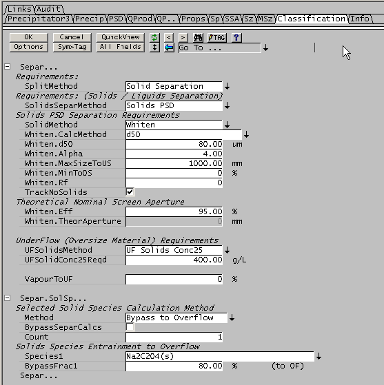
- In the classification tab
- SplitMethod as 'Solids Separation' and SolidsSeparMethod as 'Solids PSD' will be selected automatically
- Choose an appropriate PSD separation method: Partition Curve, Whiten, etc. and configure.
- Choose the UFSolidsMethod (UFSolidsMethod) e.g. UF Solids Conc25 and configure this.
- You may also separate individual selected solids, e.g. Na2C2O4(s), by configuring the Selected Solids Calculation Method.
In the results section of the Classif Tab there are extra fields displayed: UF.SolidsTakeoffQm, UF.SolidsTakeoffFrac and UF.FinalSf. The SolidsTakeOff values represent the internal Solids recycle numbers, which are equivalent of P_007 in the full configuration (left image).
The Separation Results: UFSolidsRecovery and UFLiquidRecovery variable refers to the internal classifier prior to recycle. This is equivalent to "Classifier" in the full configuration (left image)
When classification is used, we display an effective solids residence time, since the solids in the underflow remain in the tank much longer than the liquor. This is shown on the first tab page (Precipitator3):
Classifier Error Conditions
- Insufficient Solids in UF to achieve specified concentration The cut point for PSD separation is too large and not enough solids are available from the underflow to achieve the classification concentration. Reduce the cut point.
Convergence and Errors
The model solves iteratively to converge a number of key parameters
- The Yield rate at tank conditions is equal to the mass transfer
- When full PSD is on, rates of change of particle numbers in each size equal the numbers entering less the numbers leaving
- When classification is on, material is retained internally so that the underflow solids concentration equals the tank solids concentration
The overall convergence parameter is the Convergence.Limit, and the model is converged when the relative change in all the key parameters is less than this limit. In the simple case of a non-psd model only the yield error is used; if full PSD is on, then the numbers contribute as well. The Solution Convergence section in the access window shows these errors individually and in total.
In a full plant model or even a large whiteside model with recycle streams, there is little point in requiring strict convergence of individual precipitation tanks at each SysCAD iteration, since at the next iteration inlet conditions will have changed, especially early in the overall solution. The plant model will take several hundred or even thousands of overall iterations to converge, and this will allow the internal models to converge. In this it is possible to disable the PSD Number errors and Classification convergence errors, and the overall model will still converge.
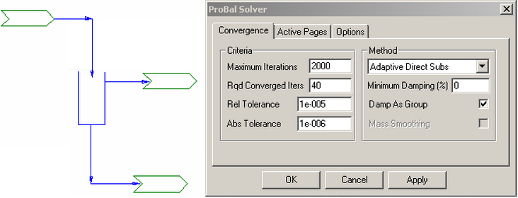
If you have a single precipitation/classification tank which is not part of a larger model, this may not converge when SysCAD is run because the internal classification recycle may not have converged fully; the easiest way to force convergence is to increase the number Rqd Converged Iters in the Probal Solver Setup dialog:
If a classifying precipitator is part of a circuit, this issue doesn't arise, because the internal state converges rapidly.
Bypassing
If a precipitator is poorly mixed, then some of the input stream may never enter the tank and simply bypass directly to the outlet. This typically occurs when row tanks are connected by launder weirs which are simply open overflow channels running from one tank to the next. The model allows for bypassing by specifying a fraction of the incoming flow to pass directly to the outlet.
Thermal Modelling
- There are a number of options related to thermal energy balance.
- Normally, the unit model will calculate HOR, cooler losses and so on, then apply a correction to the tank temperature based on these determinations. However in some circumstances it may be desirable to simply specify the final tank temperature directly, either as a temperature drop from the liquor inlet temperature, or even as a fixed final temperature. These cases may be physically unrealistic and should be used with care, however the ability to override the internal thermal calculations is there.
- Ambient Interactions
- The unit also allows thermal and mass loss to the environment. Thermal losses are due to convective cooling on the tank and free surface. There can also be mass losses due to evaporation at the free surface for an open tank; this mass loss is accompanied by a thermal loss due to evaporative latent heat.
- There is a simple ambient loss model and a more detailed model which accounts for wind speed effects. The more detailed model calculates a heat or evaporation loss per unit area, so the actual tank geometry is needed.
- If evaporation loss is implemented a stream may optionally be connected to accumulate the lost vapour.
Thermal Override
If Thermal Override is selected, then other thermal calculations have no effect. Cooler calculations are still performed, so that the performance of the coolers is still available, but they do not affect the actual final temperature.
Options for Thermal Override is:
- TempDrop : user specifies the temperature drop required.
- ProductT : user specifies the product temperature.
NOTE: If thermal override is being used, ThermalLossMethod (see next heading) is NOT available.
Thermal Loss Method
An additional thermal loss (or gain) may be specified by this selection, which is only available if Thermal Override is disabled. It is applied in addition to any cooler or reaction heats.
The available ThermalLossMethods are:
- TempDrop: User specifies a temperature drop.
- FixedLoss: User specifies a fixed energy loss. A fixed thermal loss can be used to model internal or external cooling in a simplified fashion.
- Ambient: The energy loss is calculated by ThermalLossAmbient Rate([math]\displaystyle{ K_a }[/math]) and dT between precipitator and Ambient:
[math]\displaystyle{ HeatLoss = K_a \times (T - T_A) }[/math] - WindAmbient: The energy loss is calculated by WindLossRateK ([math]\displaystyle{ K_w }[/math]), dT between precipitator and Ambient, Tank surface area and wind speed:
- [math]\displaystyle{ HeatLoss = K_w \times (T - T_A) \times TankSurfaceArea \times WindSpeed^{0.4} }[/math]
- Wind Speed can be specified locally or at the PlantModel | Environment Tab.
- NOTE: if no windspeed is specified, then a minimum of 2.5 m/s wind speed is used.
- WindAmbient2: The energy loss is calculated by WindLossRateK ([math]\displaystyle{ K_{w2} }[/math]), dT between precipitator and Ambient, Tank surface area and wind speed:
- [math]\displaystyle{ HeatLoss = K_{w2} \times (T - T_A) \times TankSurfaceArea \times WindSpeed^{0.42} }[/math]
- Wind Speed can be specified locally or at the PlantModel | Environment Tab.
- NOTE: if no windspeed is specified, then a minimum of 1 m/s wind speed is used.
Evaporation
Losses of water due to evaporation can be important and these also lead to significant overall thermal losses because of the latent heat of evaporation. Evaporation may be specified as:
- Fixed - constant mass rate or
- Ambient - proportional to ambient temperature difference.
Using the constant mass rate, it is possible to implement a function in PGM to calculate evaporation.
From Build 139 a Vent connection is required else evaporated vapour is sent to the Product stream (with a warning).
For an example of a user defined Evaporation Correlation, please see Example Evaporation Correlation.
