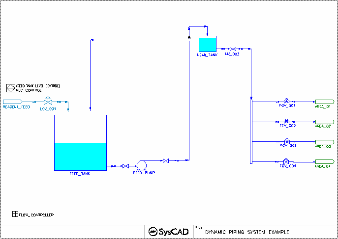
Piping System Example Project
Jump to navigation
Jump to search
Navigation: User Guide ➔ Dynamic Example Projects ➔ Piping System
Project Location
This is a Dynamic Simple project and is stored at:
..\SysCADxxx\ExamplesDynamic\Piping System Example.spf
Features Demonstrated
- Demonstrates how to use Piping System Model to set up a project to take into account pressure change.
Brief Project Description
This is a very simple flow based project where
- Feed is being pumped to a head tank
- Head tank supplies flow to downstream equipment. Excess amount is recycled to the feed tank.
- Feed tank level is maintained via fresh reagent feed.
Project Configuration
- Setting Up Piping System
- Tanks with Static Head
- On the Feed Tank and Head Tank, go to the "Settings" Tab and tick the option "WithStaticHead".
- PipingSystem Tab
- Set the Flow Estimate Method and inlet and outlet pressure
- Specify the number of segments in the piping system.
- Choose each segment type:
- Adding Head Tank Level - if flow comes from a tank with elevation, user should add in a Head Segment to allow for elevation specification.
- Adding pressure drop in pipe - pipe sections should be added to specify pipe length, change of elevation, friction factor etc.
- Adding Valve - to include pressure drop across the valve
- Adding pump - to include pressure boost
- Control Tab - if the piping system contains valve/pump, they will be visible on this tab, user can set the valve opening position or pump running speed here, as well as commands to open/close the valve or start/stop the pump.
- Settings Tab - Use this tab to define the settings for each segment.
- The piping System does not allow flow split. In the case of flow distribution, each split would require a piping system model. See valves FCV_001 to FCV_004.
