Links Table 138
Navigation: Models ➔ Common Sections ➔ Links
This page is for Build 138. Earlier versions of SysCAD may have different tags and table layout. For Build 139 or later, please refer to Links Table.
General Description
This sections details the 'Links' page for all units in SysCAD. The Links tables displayed on the Links page give different summaries of the Input and Output streams. Units in Dynamic projects will have additional Direct Links for Spill and Vent streams, but otherwise the tables will be similar. Please see Area Model Links Table for a description of the Links tables for the Area models.
The image below is from a Dynamic project, and shows the information displayed in the different tables:
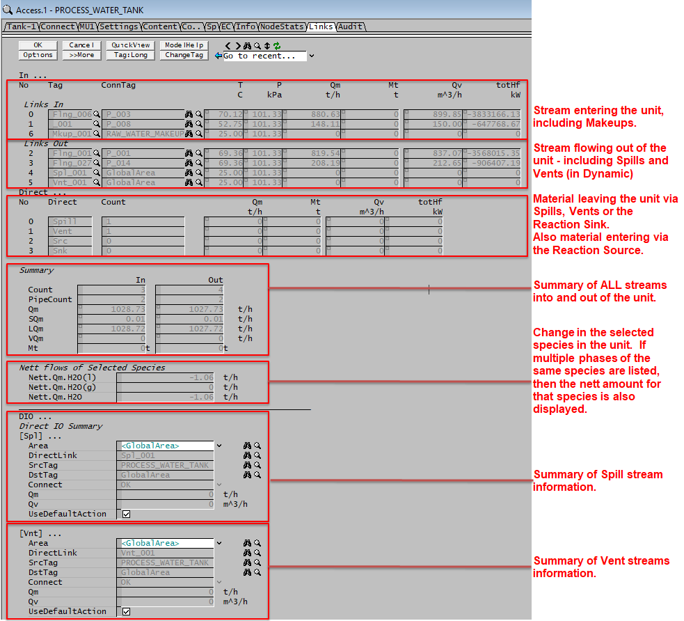
Tables: In, Out and Direct Links
The column headings for the first 3 tables, LinksIn, LinksOut and Direct are described here.
| Column Heading | Description |
| The following 4 fields are only displayed in the Links In and Out tables. | |
| LinksIn or LinksOut | The internal SysCAD Link name, Flng=Flange. Direct links are also displayed as Spl = Spill and Vnt = Vent. |
| ConnTag | Link Name Or Source Name for Direct links such as Makeups, Spills and Vents. |
| T | The temperature of the material flowing through the link. |
| P | The pressure of the material flowing through the link. |
| The following 2 fields are only displayed in the Direct Links table. | |
| Direct | The type of Direct link - there are 4 types: Spill, Vent, Src (Reaction Source) and Snk (Reaction Sink). |
| Count | The number of Direct Links of each type, either 0 or 1. |
| All of the following fields are displayed in the Links In and Out and the Direct Links tables. | |
| No | The link number. Links are numbered from 0. |
| Qm | Mass flow through the link. The user may choose to display this in any conversion units. |
| Mt | Only visible in Dynamic projects. Total Mass that has flowed through the link in the current SysCAD run. The user may choose to display this in any conversion units. |
| Qv | Volumetric flow through the link. The user may choose to display this in any conversion units. |
| totHf | Total Heat of formation at stream conditions. The user may choose to display this in any conversion units. |
Summary Table
| Tag | Description |
| The summary is displayed in a table format, listing the total In and Out summary information. | |
| Count | The total number of in and out links connects to the unit - this includes all pipes, Makeups, spills and vents. |
| PipeCount | The total number of in and out links connects to the unit - does not include Makeups, spills and vents. |
| MassFlow / Qm | The total flow rate from all links entering and leaving the unit - this includes pipes, Makeups, spills, vents and Reaction Source and sink. |
| SolidMassFlow / SQm | The Solids only flow rate from all links entering and leaving the unit - this includes pipes, Makeups, spills, vents and Reaction Source and sink. |
| LiquidMassFlow / LQm | The Liquids only flow rate from all links entering and leaving the unit - this includes pipes, Makeups, spills, vents and Reaction Source and sink. |
| VapourMassFlow / VQm | The Vapours only flow rate from all links entering and leaving the unit - this includes pipes, Makeups, spills, vents and Reaction Source and sink. |
| TotalMass / Mt | Only visible in Dynamic projects. Includes: in: The total Mass that has entered the unit from all links in the current SysCAD run - this includes pipes, Makeups and Reaction Sources. out: The total Mass that has exited from the unit from all links in the current SysCAD run - this includes pipes, Spills, Vents (in Dynamic) and Reaction Sinks. |
Species Table
This table displays the mass change for selected species across the unit. In Feeders and Sinks this will be due to adding or removing material, in other units it will be due to reactions.
This allows users to produce a mass balance for selected species across either the entire project, or selected areas.
The default species that will be displayed are H2O(l) and H2O(g). However, the user may add additional species, and remove water and steam if required - go to View - Plant Model and see the List of Species to Report nett flows (shown of the Links page):. See NettQm.List on Plant Model Access Window.
Notes:
- This is NOT the amount of the species flowing into and out of the unit in Links.
- This is the amount of the species that actually enters or leaves the project, or is created or consumed in Reactions.
| Tag | Description |
| Configuration | |
| Nett.Qm.Water(l) / H2O(l) | Displays the mass change of water. This would be 0 if water is not consumed or created. Used to keep track of compound change in reactions & phase change. |
| Nett.Qm.Steam(g) / H2O(g) | Displays the mass change of steam. This would be 0 if steam is not consumed or created. Used to keep track of compound change in reactions & phase change. |
| Nett.Qm.H2O | This variable is automatically added. When a species is added to the list in multiple phases, an extra field is added to show the nett change of the species. For example, Nett.Qm.H2O = Nett.Qm.H2O(l) + Nett.Qm.H2O(g). This is very useful when creating water/steam balances for the project. |
| Nett.Qm.xxx(phase) | Other compounds maybe visible if the user has added species on the Plant Model - Settings Tab, heading Link Balance Species. |
| Nett.Qm.xxx | If multiple phases of the same species are added to the Link Balance Species List, then the species (with no phase specified) will be added automatically to the links table to show nett change for the species. See example for H2O above. This nett flow is useful for component balances. |
Direct IO Summary
These fields appear whenever there is some form of DirectLink connected to the model. This includes:
- Models with Makeups;
- In Dynamic projects for units that have a content (e.g. Tanks) that may have slurry spills and vent spills;
- In Dynamic projects units or pipes may have spills;
The table below describes the fields of a Slurry Spill and Vent Spill:
| Tag / Symbol | Input/ Display | Description |
|---|---|---|
| Area | Drop Down List | The Area to which any spills will be sent. This is normally the Global Area. |
| DirectLink | Display | The tag of the spill direct link. |
| SrcTag | Display | The tag of the source unit of the spill direct link, i.e. the tank. |
| DstTag | Display | The tag of spill direct link's destination unit - This will be the area specified in the Area field. |
| Connect | Display | Provides feedback on if connection is valid. |
| MassFlowEst / QmEst | Calc | Estimated mass flow of spill. |
| MassFlow / Qm | Calc | Current mass flow of spill. |
| VolFlow / Qv | Calc | Current volume flow of spill. |
| NVolFlow / NQv | Calc | Current normal volume flow of spill. |
| Similar sets of information will be shown for any other direct links attached to the tank such as Makeup direct links. | ||