General Options Drawing
Jump to navigation
Jump to search
Navigation: User Guide ➔ Menu Commands ➔ Tools ➔ General Options ➔ Drawing
| General | Access | Find | Toolbars | Project | Graphics | Drawing | Colours | Mouse | Trends | TagList |
|---|
Drawing
| Group | Option | Description | |
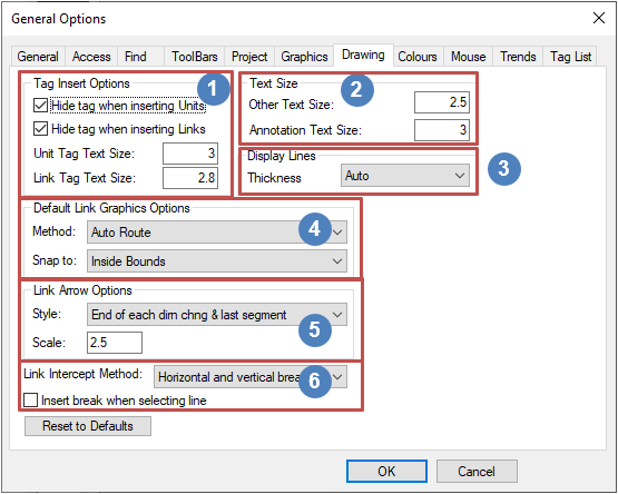
Tag Insert Options |
Hide tag when inserting units | This will hide the tag for any newly inserted units. This is equivalent to ticking the Hide Tag box on the Insert Unit dialog box. | |
| Hide tag when inserting links | This will hide the tag for any newly inserted links. This is equivalent to ticking the Hidden box on the Insert Link dialog box. | ||
| Unit Tag Text Size | This will set the default size of all tags when inserting Units; OR when Graphics - Display - Size All Unit Tag command is used. | ||
| Link Tag Text Size | This will set the default size of all tags when inserting Links; OR when Graphics - Display - Size All Link Tag command is used. | ||
Text Size |
Other Text Size | This will set the default size when pasting raw text from the clipboard (using the Graphics - Copy & Paste or ctrl+v commands). | |
| Annotation Text Size | This will set the default size when creating the annotation block. | ||
Display Lines Available from Build 139.32925. |
Thickness | This sets the line thickness (i.e. weight, width) of all graphics (lines and text) displayed in the in the graphics window. | |
| Thin - 1 Pixel | Lines are always 1 pixel thick. | ||
| Thin - Adaptive | Thin lines which get thicker depending on graphics window and drawing size. | ||
| Thick - Adaptive | Thick lines which get thicker depending on graphics window and drawing size. (Especially useful for screen sharing or projection.) | ||
| Auto | Automatically selects between Thin - 1 Pixel and Thin - Adaptive depending on screen DPI. | ||
Default Link Graphics Options |
| ||
| Method: | No Route | SysCAD will NOT automatically draw a link, the user must manually draw the link. | |
| Single Segment | A single straight line will be drawn between the two selection points. | ||
| Auto Route | This is the Default and recommended method. A combination of straight horizontal and vertical line(s) will be drawn between the two selection points. | ||
| Snap to: | This defines where SysCAD will place the start and end points on the Source and Destination units. | ||
| No Snap | Use the digitized points only. | ||
| Unit Centre | Use the centre of the Source and Destination units. | ||
| Auto Select | Always selects the closest edges of the Source and Destination units, no matter where you click. | ||
| Nearest Graphics | Snap to the nearest point on the graphic of the Source and Destination units. | ||
| Inside Bounds | This is the Default method. Will NOT snap to a point if you are inside the bounding box; snaps to the edge of the unit if you are outside the bounding box. | ||
| Bounds Edge | Snap to the nearest point on the bounding box. | ||
| Centre Bounds Edge | Snap to the nearest point on the bounding box in the normal direction, and the centre in the transverse direction. | ||
| Bounds Distribute | Allows you to space the connection points equally along the edge. Currently the side is divided into six equal segments (so that there are five points along the edge to which you may snap. For three points on the edge you can snap to the mid point, 25% and 75%. | ||
Link Arrow Options |
Style | Link Arrow Options | Where to display the arrow on the Link. This will set the default options for Insert Link & Redraw Link and also links pasted using the Copy&Paste Graphics options. |
| Scale | The arrow size. This will set the default options for Insert Link & Redraw Link and also links pasted using the Copy&Paste Graphics options. | ||
Link Intercept Method |
This allows the user to define how the automatic link breakages occur. Please see Link Intercept Methods for a more detailed description of the options. | ||
| None | SysCAD will NOT automatically break the link if it crosses another link. User can fix all the breaks when the flowsheet is finished by using Graphics - Display - Horizontal Break at Link Intercept or Vertical Break at Link Intercept command. | ||
| Horizontal and Vertical Breaks | This is the Default. SysCAD will automatically break the link if it crosses another Horizontal OR Vertical link. | ||
| Horizontal Breaks Only | SysCAD will automatically break the link if it crosses another Vertical link. | ||
| Vertical Breaks Only | SysCAD will automatically break the link if it crosses another Horizontal link. | ||
| Insert break when Selecting line | For users using the NONE Link intercept method, breaks may be "manually" added when user clicks on the crossing link. | ||
| Reset to Default | Pressing this button will reset all Options on the current tab to default settings. | ||
