Example Potash Projects
Navigation: User Guide ➔ Example Projects ➔ 50 Potash
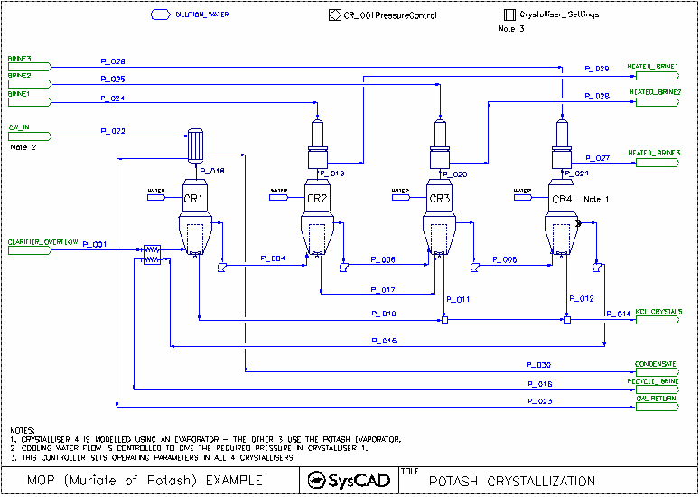
Four Stage Crystallisation Example Project
Project Location
This is a Steady State project and is stored at:
..\SysCADXXX\Examples\50 Potash\Four Stage Crystallisation Example.spf
Features Demonstrated
- Setting up flash trains using PotashEvaporator with Shell and Tube Heat Exchanger 2 & Barometric Condenser.
- Use of the Potash Solubility Functionality
Brief Project Description
- This is a MOP (Muriate of Potash) example project.
- This project shows a 4-Stage-Evaporator(crystalliser) circuit.
- This project uses constant feed for Liquor Feed and Brine streams.
- Crystallisation is based on Potash solubility data.
- Dilution water is added to each crystallisation stage.
- PotashEvaporator underflow (crystallised material) is removed from the first third and fourth stage. Second stage underflow is feed to the 3rd stage.
- Brine is used to exchange heat in the Barometric condensers.
Project Configuration
PotashEvaporator
- PotashEvaporator Tab
- Select FlashTrain mode
- Specify minimum flash temperature for the unit (this will assist with pressure balance of the circuit)
- Select Solubility On (for Body Evaluation Block Only)
- Define the Fraction of Leg feed liquid reporting to the Evaporator.
- Define the Overflow and Product Splits.
- Optional - Makeup block - used to add dilution water to the crystalliser.
- PC Tab
- Select the Potash solubility System. NOTE the Potash Solubility data requires the Potash Addon.
- Select the Solubility (Potash) Calculation Configuration.
Barometric Condenser
- Set the approach temperature.
Shell and Tube Heat Exchange
- HX_001 is used to condense the flash steam from the 1st Crystalliser,
- Method - CondensingSteam
- Condensing Method: Demand (UA)
- Demand Connection: FlashTrain
- The condenser area and HTC information is supplied.
- HX_002 is used to preheat the feed with recycle Brine
- Method - Sensible HX
- The heater area and HTC information is supplied.
Included Excel Reports
- Potash Crystalliser Report Rev 0.xls - This file includes the following reports:
- Criteria
- Crystalliser Conditions
- Streams
- Flowsheet
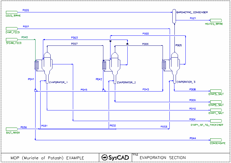
Three Stage Evaporator Example Project
Project Location
This is a Steady State project and is stored at:
..\SysCADXXX\Examples\50 Potash\Three Stage Evaporator Example.spf
Features Demonstrated
- Setting up flash trains using PotashEvaporator with embedded heat exchanger and Barometric Condenser.
- Use of the Potash Solubility Functionality
Brief Project Description
- This is a MOP (Muriate of Potash) example project.
- This project shows a 3-Stage-PotashEvaporator(crystalliser) circuit.
- This project uses constant feed for Liquor Feed, Steam and cooling water supply.
- The evaporators have embedded heat exchangers enabled
- Crystallisation is based on Potash solubility data.
- Evaporator underflow (crystallised material) is removed from each stage.
- Salt Wash is added to each stage (Leg Feed).
Project Configuration
Evaporator
- PotashEvaporator Tab
- Select FlashTrain mode
- Specify minimum flash temperature for the unit (this will assist with pressure balance of the circuit)
- Select Solubility On (For Both Body Evaluation and Leg Evaluation Blocks)
- Define the Fraction of Leg feed liquid reporting to the Evaporator.
- Define the Overflow and Product Splits.
- Select Evaporator Heat Exchanger Option
- HX Tab - The Embedded Heat Exchanger has been defined, this includes the number of heat exchanges, size and heat transfer coefficient.
- PC Tab (Body Evaluation Block Solubility On)
- Select the Potash solubility System. NOTE the Potash Solubility data requires the Potash Addon.
- Select the Solubility (Potash) Calculation Configuration.
- LPC Tab (Leg Evaluation Block Solubility On)
- Select the Potash solubility System. NOTE the Potash Solubility data requires the Potash Addon.
- Select the Solubility (Potash) Calculation Configuration.
Barometric Condenser
- Set the approach temperature.
Included Excel Reports
- Potash Evaporator Report Rev 0.xls - This file includes the following reports:
- Criteria
- Evaporator Conditions
- Streams
- Flowsheet
SOP Example Project
Annual Climate Data for Dynamic Modelling |
Project Location
This is a Steady State project and is stored at:
..\SysCADXXX\Examples\50 Potash\SOP Example Project.spf
Features Demonstrated
- The use of Discard Blocks and Discard Sinks
- The use of Model Procedures
- The use of a PGM Class
- The use of Makeup Sources and Makeup Blocks
- The use of the Link to MakeupSrc Operation in Feeder model
- The use of Reaction Blocks, including the use of Override Product Temperature Option
- The use of the Flotation Cell model
- The use of the Evaporator model as a crystalliser
- The use of the Filter Press model
- The use of the Evaporation Block (Evap) sub-model
- The use of Split Flows Solids Recovery option
- The use of a PID Controller
- The use of a Set Tag Controller
- The use of General Controllers
Brief Project Description
- This is an SOP (Sulphate of Potash) example project.
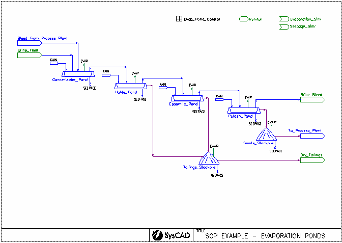
- This is a simplified model of a brine stream being concentrated in a series of evaporation ponds and the precipitated solids refined in a processing plant to produce an SOP Product.
- The four evaporation ponds have the following in common:
- A common Model Procedure which sets the Rainfall, Evaporation and Seepage in the pond.
- The rainfall, evaporation and seepage rates are set by the Evap Pond Control General Controller.
- For each pond, the user can set the Mode (Design or Operation), Catchment Ratio, Evap Ratio and whether the pond is lined.
- In Design Mode, the user sets the desired Evaporation Fraction and the model calculates the required Surface Area. In Operation Mode, the user sets the Surface Area.
- Based on the user inputs, the model procedure calculates the required rainfall rate and sets the Makeup Block.
- Based on the user inputs, the model procedure calculates the required evaporation rate (Operation Mode) or evaporation fraction (Design Mode) and sets the Evap Block.
- Based on the user inputs, the model procedure calculates the required seepage rate and sets the second Discard Block.
- Dissolution and precipitation reactions occur in the ponds.
- The temperature of the pond is maintained at 25 °C.
- The first Discard Block sends all gases to the Evaporation Sink Discard Sink.
- A brine stream and a bleed from the Process Plant are fed to the Concentrator Pond. All solids in the feed are dissolved and some Gypsum is precipitated. The remaining material is sent to the Halite Pond.
- In the Halite Pond some Gypsum and Sodium Chloride precipitate. All of the solids and some of the remaining liquids are sent to the Tailings Stockpile. The remaining material is sent to the Epsomite Pond.
- In the Epsomite Pond some Gypsum, Sodium Chloride and Epsomite precipitate. All of the solids and some of the remaining liquids are sent to the Tailings Stockpile. The remaining material is sent to the Potash Pond.
- In the Potash Pond some Kainite and Sodium Chloride precipitate. All of the solids and some of the remaining liquids are sent to the Kainite Stockpile. The remaining material is sent to the Brine Bleed sink.
- In the Tailings Stockpile Gypsum, Sodium Chloride, Epsomite and Kainite precipitate. Some of the water evaporates and some of the remaining liquids are sent to the Seepage Sink until the remaining liquid fraction is 2%. The temperature of the stockpile is maintained at 25 °C. The remaining material is sent to the Dry Tailings sink.
- In the Kainite Stockpile Gypsum, Sodium Chloride, Epsomite and Kainite precipitate. Some of the water evaporates and some of the remaining liquids are sent to the Seepage Sink until the remaining liquid fraction is 1.5%. The temperature of the stockpile is maintained at 25 °C. The remaining material is sent to the Process Plant.
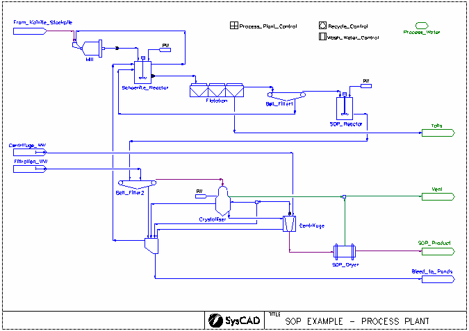
- Dried Kainite is slurried and fed through a Mill (size distribution is not modelled) and then into the Schoenite Reactor, where it is mixed with recycle streams. If required, process water is added to achieve a solids fraction of 22%.
- In the Schoenite Reactor, Kainite is converted to Schoenite, as well as some further precipitation of Sodium Chloride and Epsomite. These reactions occur at 40 °C. The product is separate into a Schoenite slurry (35% solids) and a clear brine that is sent back to the Mill to slurry the dried Kainite feed.
- The Schoenite slurry is fed to Flotation where the Sodium Chloride preferentially floats. The loss of Schoenite is limited to 10% by setting its recovery to the concentrate stream. The concentrate (impurity) stream is sent to the Tails sink. The purified Schoenite slurry is fed to Belt Filter 1.
- The cake from Belt Filter 1 is sent to the SOP Reactor while the filtrate is recycled back to the Schoenite Reactor.
- In the SOP Reactor, Schoenite is converted to Potassium Sulphate (SOP). The reaction occurs at 50 °C. Process water is added to achieve a solids fraction of 40%.
- The slurry is sent to Belt Filter 2 where it is washed with process water. The Wash Water Control is used to set the wash water flow based on a ratio to the solids feed to the filter. The washed filter cake is sent to the Crystalliser.
- A fixed flow of process water is added to incoming slurry in the Crystalliser. Then various precipitates redissolve, any leftover Schoenite is converted to Potassium Sulphate (SOP) and most aqueous Potassium Sulphate is precipitated. The reactions occur at 80 °C. The pressure of the Crystalliser is set at 30kPa. The temperature and pressure conditions result in the evaporation of water, as determined by the VLE sub-model. All gases are vented and the solids fraction of the product slurry is set at 30%.
- The product slurry from the Crystalliser is sent to the Centrifuge where it is washed with process water. The Wash Water Control is used to set the wash water flow based on a ratio to the solids feed to the filter. The washed filter cake is sent to the SOP Dryer.
- The Belt Filter filtrate, Crystalliser overflow, Centrifuge washing and a bleed of the Centrifuge centrate are combined. The Recycle Control is used to send a fraction of this to the Schoenite Reactor to achieve a solids fraction of 22%. The remaining material is sent back to the Concentrator Pond.
- In the SOP Dryer, all water is evaporated and aqueous species are returned to their solid forms. The reactions occur at 80 °C. The steam is vented leaving the solid SOP product.
Project Configuration
- Most units with reactions are simulated by the Tank model. This includes the evaporation ponds, stockpiles, Schoenite Reactor, SOP Reactor and SOP Dryer. In all cases, the Override Product Temperature Option is used to set the desired temperature.
- Makeup Blocks are used:
- in all 4 evaporation ponds to add a fixed volume of rain
- in the Schoenite and SOP Reactors to add process water to achieve a specified solids fraction
- in the Crystalliser to add a fixed mass flow of process water
- Discard Blocks are used:
- in all 4 evaporation ponds and the two stockpiles to send all of the gases to the Evaporation Sink using the Fraction Discard option.
- in all 4 evaporatioin ponds to send a fixed volume flow of liquids which seep through the bottom of the pond to the Seepage Sink using the Fixed Discard option.
- in the Tailings and Kainite Stockpiles to achieve a specified solids fraction using the Product Composition option.
- All 4 evaporation ponds use a common Model Procedure which sets the Rainfall, Evaporation and Seepage in the pond.
- All 4 evaporation ponds use the Evap Block to model the evaporation of water from the pond.
- In the last 3 evaporation ponds, all of the solids and some of the remaining liquids are sent to the Stockpiles using the Split Flows Solids Recovery option.
- Similarly, in the Schoenite Reactor, all of the solids and some of the liquids are sent to Flotation using the Split Flows Solids Recovery option.
- The Filtration WW and Centrifuge WW Feeders uses the Link to MakeupSrc Operation to link to the Process Water Makeup Source.
- The Flotation Cell model is used to model the flotation process using the Mass Pull & Recovery method to specify the required recovery of Sodium Chloride to the concentrate stream. The loss of Schoenite is limited to 10% by setting its recovery to the concentrate stream.
- The Belt Filters and Centrifuge are modelled by the Filter Press model using the SolidsFractionInFiltrate and Constant Wash Efficiency methods.
- The Crystalliser is modelled by the Evaporator model in Stand Alone mode. This model automatically includes the use of the VLE sub-model to flash vapours and send them to the vent stream. The pressure of the unit is set and the fraction of solids in the product slurry is set using the Solid Separation SplitMethod.
- Separation of gases and solids in the SOP Dryer is achieved by the use of Split Flows Gas Vent option.
- Splitting of the Centrifuge centrate and combined bleed stream to different streams is achieved by the use of Split Flows Mass Frac option.
- A Set Tag Controller is used to set wash water flows based on user specified ratios to the Belt Filter and Centrifuge.
- A PID Controller is used to control the combined bleed stream split in order to achieve the desired solids fraction in the feed to the Schoenite Reactor.
- General Controllers are used to:
- send common input parameters to all 4 evaporation ponds.
- display overall flows.
- display results for each pond using a PGM Class.
- calculate recoveries.


