Example - GFEM Projects
Navigation: User Guide ➔ Example Projects ➔ 03 UnitModels: Gibbs FEM Projects
Related Links: Reactor (Gibbs FEM)
GFEM Simple Examples
- (NOTE: not all the flowsheets are shown here)
Project Location
..\SysCADXXX\Examples\03 UnitModels\GFEM Simple Examples.spf
Features Demonstrated
Shows how to set up simple Gibbs Free Energy Minimisation Reactors.
Brief Description
This project has five flowsheets:
- Single Reform Reaction
- Shows how to set up a single reaction in the Gibbs FEM reactor, this is compared to using the reaction block.
- Multi Species Reform Reaction
- Shows how to set up the Gibbs FEM where two reactions are present.
- Hydrazine Combustion
- Shows how to set up the combustion reactions. This example highlights an issue where chemical potential values may need to be overridden due to poor data in the database at very high temperatures.
- Vapour Liquid Equilibrium
- Shows how the Gibbs FEM reactor can be set up to find VLE or Boiling point of mixtures.
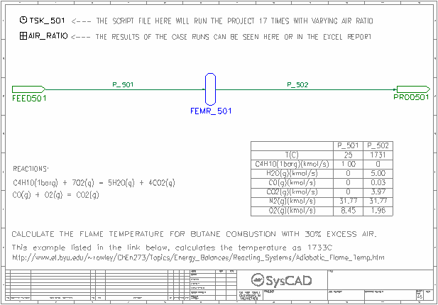
- Adiabatic Flame Temperature
- Shows how the Gibbs FEM reactor can be set up to find the adiabatic flame temperature.
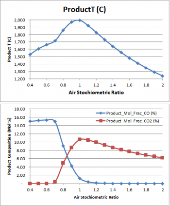
- This page also shows the CO and CO2 fraction change based on feed air ratio.
Project Configuration
The project configuration has been described in detail in the SysCAD Supplementary Tutorial - Gibbs FEM.pdf.
Included Excel Report
CO & CO2 Composition.xlsx - This workbook contains results from the Adiabatic Flame Temperature flowsheet.
GFEM Blast Furnace Examples
Project Location
..\SysCADXXX\Examples\65 Smelting\GFEM Blast Furnace Examples.spf
Features Demonstrated
Shows how to set up Blast Furnace using Gibbs FEM reactors.
Brief Description
This project has two flowsheets:
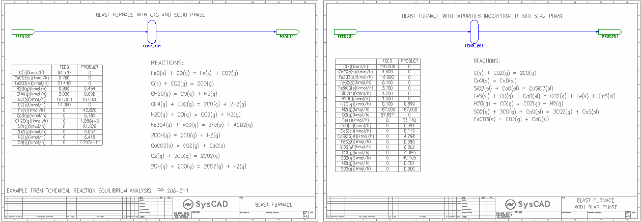
- Blast Furnace
- Shows how to set up the blast furnace reactions using the Gibbs FEM reactor, this page considers only the solid and gas phase.
- Blast Furnace with Slag
- Shows how to set up the blast furnace reactions using the Gibbs FEM reactor, this page has included the impurities into the slag phase.
Project Configuration
The project configuration has been described in detail in the SysCAD Supplementary Tutorial - Gibbs FEM.pdf.
Green Steelmaking Example
Project Location
This is a Steady State project and is stored at:
..\SysCADXXX\Examples\66 Steelmaking\Green Steelmaking Example.spf
Features Demonstrated
Shows how to use Gibbs Free Energy Minimisation (Gibbs FEM) Reactors with non-ideal solution models by adding automatic calculation of activity coefficients for the monoxide phase in a PGM (General Controller) as a function of composition and temperature using R-K (Redlich-Kister) model.
Use of magnetic ordering parameters for Gibbs Energy equations (GibbsMag_Cp) for Fe (bcc and fcc) and Spinel (Fe3O4) compounds.
Brief Description
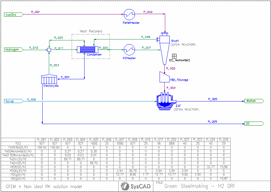
The model consists of a high-level DRI (Direct Reduction of Iron) process driven by H2(g) reduction. The iron ore feed consist of hematite (Fe2O3) at a mass flow rate of 100 t/h.
Excess pre-heated hydrogen gas is necessary to be provided to the shaft furnace to drive the reduction reaction from monoxide (FeO solid solution) to metallic Fe (bcc or fcc) due to thermodynamic constrains.
The Shaft furnace off-gas contains a significant fraction of un-used H2(g) that needs to be recycled and H2O(g) resulting from the reduction reactions. However, the water vapour must be condensed and removed from the recirculating gas by means of heat exchangers.
The condensed water from the off-gas is electrolyzed to regenerate H2(g). Since this process is not 100% efficient, make-up hydrogen (fresh feed) is necessary to balance the process requirements.
The hot reduced iron product from the shaft furnace are feed into an electric arc furnace (EAF) where it can be melted alongside recycled scrap.
The shaft furnace and EAF are GFEM reactors. The shaft furnace includes PGM code (General Controller) to add functionality describing the non-ideal behaviour of the binary solid solution model for monoxide (FeO - FeO1.5). This model is necessary to correctly predict the boundary line between FeO/Fe reduction at the correct H2/H2O ratio.
Project Configuration
- This model uses a specially designed thermodynamic database which includes magnetic ordering contributions to Gibbs Energy equations applicable to solid iron species (bcc and fcc) and some of spinel phases end-members.
- The database is based on the Fe-O-H system, including solid phases (s, bcc, fcc, monoxide, spinel), liquid phase (l and ml) and gas phase (g)
- Fe(bcc) is standard element reference for Iron compounds. Data for bcc, fcc and ml are taken from Dinsdale (SGTE data for pure elements, CALPHAD, vol 15, no. 5, 1991)
- Data for gas compounds is taken from McBride et. al. (NASA Glenn coefficients for calculating thermodynamic properties of individual species, NASA/TP-2002-211556)
- Data for end-members of the monoxide and spinel phases was taken from Hidayat et. al. (Thermodynamic reevaluation of the Fe-O System. CALPHAD, vol 48, 2015). In the case of monoxide phase, binary interaction parameters were optimized using the Redlich-Kister solution model and implemented into the model using a PGM code (General Controller GC_monoxide2)
- The main reacting unit is the Shaft furnace, modelled using a Gibbs Free Energy Minimization reactor (GFEM) at a fixed temperature (defined in the GC_monoxide2 controller). Two solid solutions are set in the GFEM reactor (Phase 1 for monoxide and Phase 2 for spinel). Activity coefficients for monoxide are calculated and set by the R-K model from the GC_Monoxide2 code as a function of composition and temperature.
- The electric arc furnace is modelled also by a GFEM reactor where either Fe(bcc), Fe(fcc) and any residual monoxide species are melted into Fe(ml). Since this model does not include the use of any fluxing agent, no slag is formed at the EAF.
- The Condenser is modelled using a Tank model with a reaction block for the condensation of H2O(g) to H2O(l) using a fixed extent of reaction set at 92%.
- The Electrolysis unit to recover H2(g) is also modelled using a tank with a reaction block, where the final flow of H2 is specified to a fixed value of 2 t/h
- A simple heater unit model is used for the pre-heating stages of iron ore and hydrogen before entering the Shaft furnace. The product temperature is specified using fixed values.
- The model considers the recirculation of process gas. Additional fresh hydrogen needs to be supplied to the system by a feeder, which is set by a fixed mass flow rate. Alternatively the recirculating flow can be set by demand at pipe P_011 and activating Demand On at the Hydrogen feeder. The flow of recirculating gas is determined by the thermodynamic constrains at the Shaft furnace for the reduction of FeO from the monoxide phase into metallic Fe as a function of temperature and equilibrium concentration of gases.
References
- "Practical and Theoretical limitations of Green Steelmaking - A process simulation perspective", COM 2023, The 62nd Annual Conference of Metallurgist, Wasmund Memorial Symposium of Sustainability in Pyrometallurgy (pre-recorded presentation)
- "Modelling non-ideal binary solutions using SysCAD GFEM", ExMente Pyro Community Day 2023


