Example - 05 PHREEQC Projects
Navigation: User Guide ➔ Example Projects ➔ 05 PHREEQC
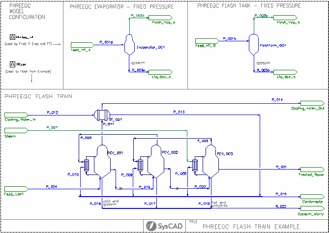
Evaporators Example
Project Location
..\SysCADXXX\Examples\05 PHREEQC\PHREEQCLight\Evaporators Example.spf
Features Demonstrated
- The use of PHREEQCModelCfg
- The use of PHREEQCEvaporator
- The use of PHREEQCFlashTank
Brief Project Description
- Each PHREEQC project must contain at least one PHREEQCModelCfg model. There are two of these files defined here, each referencing to a different PHREEQC database.
- The PHREEQC evaporator and PHREEQC Flash Tank can both operate in standalone or Flash Train modes.
Project Configuration
- The Minteq_v4 PHREEQC database is used by the standalone Evaporator and Flash tank.
- Note that Gypsum precipitation temperature is different to the Pitzer database (used in the flash train section)
- The Minteq_v4 database has multiple equilibrium models, the Davies equilibrium model has been selected in our example.
- The Pitzer PHREEQC database is used by the flash train section of the model.
- Note that Gypsum precipitation temperature is different to the Minteq_v4 database (used in the standalone section)
- The Pitzer database does not allow multiple equilibrium models, so no selections are available.
- SatIdx of 100 for H2O(s) has been entered in the "PHREEQCConfig" tab.
- Salts First algorithm has been selected for species re-building in both Minteq_v4 and Pitzer model configuration files. See Reverse Mapping section for more details.
PHREEQC Evaporator / Flash Tank
- The configuration of the PHREEQC Evaporator / Flash Tank are very similar to the normal Evaporator and FlashTank, the main difference is to select the PHREEQC Chemistry model to be used.
RO Plant Example
Project Location
..\SysCADXXX\Examples\05 PHREEQC\PHREEQCLight\RO Plant Example.spf
Features Demonstrated
- The use of PHREEQCModelCfg
- The use of PHREEQCReverseOsmosis
Brief Project Description
- Each PHREEQC project must contain at least one PHREEQCModelCfg model.
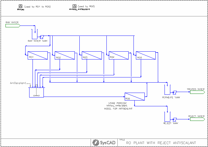
- This project demonstrates the use of the RO unit for calculating max permeate recovery.
- Influence of antiscalant. This is modelled by creating a second PHREEQC configuration where we allow supersaturation of gypsum. The concentrate RO skid (RO6) uses this configuration in its calculation of maximum permeate recovery.
Project Configuration
- The Minteq_v4 PHREEQC database is used by the RO 01 to 05 units.
- The Minteq_v4 database has multiple equilibrium models, the Davies equilibrium model has been selected in our example.
- A second Minteq_v4 PHREEQC database is used by the RO 06 unit to emulate the influence of antiscalant.
- SatIdx of 0.3 for CaSO4:2H2O(s)(Gypsum) and CaSO4(s) have been entered in the "PHREEQCConfig" tab.
- Salts First algorithm has been selected for species re-building in both Minteq_v4 and Pitzer model configuration files. See Reverse Mapping section for more details.
- The configuration of the PHREEQCReverseOsmosis is similar to the normal Reverse Osmosis (RO) Unit, the main difference are:
- select the PHREEQC Chemistry model to be used and
- model method: MaxYield for maximum permeate recovery.
Simple Reactor Example
Project Location
..\SysCADXXX\Examples\05 PHREEQC\PHREEQCLight\Simple Reactor Example.spf
Features Demonstrated
- The use of PHREEQCModelCfg
- The use of PHREEQCReactor
- The use of PHREEQCSideCalc
Brief Project Description
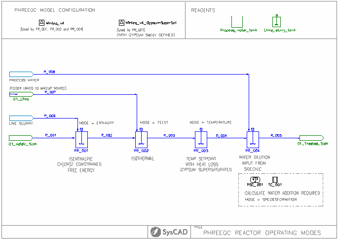
In this demo project, we demonstrate several different operating modes for the PHREEQC reactor.
- Isenthalpic, temperature of the output is calculated for an acid-base reaction
- Isothermal, temperature is set to the temperature of the incoming stream mixture, heat flow required to achieve this is calculated
- A temperature setpoint is set, heat loss is also incorporated
- This tank is linked with a side calculation. The side calculation is doing a calculation to determine the water required to dissolve the gypsum coming in to the tank. The calculated water flow is then applied to the makeup of the actual reactor tank. This demonstrates a feed-forward control strategy for water addition
- Each PHREEQC project must contain at least one PHREEQCModelCfg model.
- We have used two PHREEQCModelCfg models in this project, one we allow supersaturation of gypsum.
Project Configuration
- The Minteq_v4 PHREEQC database is used by the PR_001, PR_002 and PR_004 units.
- The Minteq_v4 database has multiple equilibrium models, the Davies equilibrium model has been selected in our example.
- A second Minteq_v4 PHREEQC database is used by the PR_003 unit to emulate the Gypsum being supersaturated.
- SatIdx of 0.1 for CaSO4:2H2O(s)(Gypsum) has been entered in the "PHREEQCConfig" tab.
- Salts First algorithm has been selected for species re-building in both Minteq_v4 and Pitzer model configuration files. See Reverse Mapping section for more details.
- PR_001
- Ca(OH)2 addition is being constrained, this is done by ticking "UseCFE" and in the CFE tab: Ca(OH)2 has 5% inert fraction.
- Calculation mode is isenthalpic (delta enthalpy = 0 kW)
- We found gypsum precipitation occurs and a slight pickup in tank temperature due to reaction. There are some Ca(OH)2 remaining due to the user specified inert fraction
- PR_002
- Calculation mode is isothermal (Final T = Feed T), heat flow required to achieve this is shown in the PHREEQCResults, Energy balance section.
- Ca(OH)2 addition is fully used and gypsum precipitation occurred
- PR_003
- Calculation mode is user specified temperature, heat flow required to achieve this is shown in the PHREEQCResults, Energy balance section.
- This reactor also uses a different SatIdx for gypsum, allowing gypsum to be supersaturated.
- Heat loss is also being used in this model.
- PR_004 and PSC_001
- The PSC_001 has been set up to determine the water required to dissolve the gypsum coming in to PR_004. The calculated water flow is then applied to the makeup of the actual reactor tank. This demonstrates a feed-forward control strategy for water addition.
USX Example
Project Location
..\SysCADXXX\Examples\05 PHREEQC\PHREEQCFull\USX Example.spf
Available from Build 139.30918.
Features Demonstrated
- The use of PHREEQC Thermodynamic Calculation Engine using a customised database.
- The use of PHREEQC Model Configuration.
- The use of PHREEQC Solvent Extraction.
- The use of PHREEQC Side Calc Model.
- The use of Solvent Extraction (Mixer/Settler) Unit with an isotherm.
- The use of the Stream Fetch operation in a Feeder.
- The use of Makeup Sources and Makeup Blocks.
- The use of the Discard Sink and Discard Block.
- The use of Reactions, including reaction override.
- The use of a General Controller.
- The use of a Set Tag Controller.
- The use of a PID Controller.
Brief Project Description
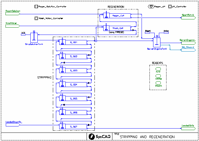
- This example project was used as the basis for a paper entitled "First Principles Modelling of the Solvent Extraction and Stripping of Uranium including Molybdenum Control", which was presented at ALTA 2022 in Perth by Kevin Heppner.
- This is a simplified model of a uranium solvent extraction (USX) plant. It is a typical plant arrangement with extraction, strong acid stripping, and organic regeneration. It is not intended to model any particular plant.
- The PHREEQC minteq.v4.dat model is used with the addition of chemistry to account for extraction of molybdenum, acid, and uranium to tertiary amine. The chemistry model was fitted to data in the open literature:
- N Yakabu and A Dudeney, “A study of uranium solvent extraction equilibria with Alamine 336 in kerosene”, Hydrometallurgy, 1987
- J. Coca, F. Diez, and M Moris, “Solvent extraction of molybdenum and tungsten by Alamine 336 and DEHPA”, Hydrometallurgy 1990.
- Stream Fetch is used to model the recirculating organic stream. The composition of the returning barren organic is fetched by the feeder to the extraction circuit.
- Pregnant aqueous solution is fed to the extraction circuit. The concentration of uranium, molybdenum, and free acid can be set in the General Controller on the extraction flowsheet.
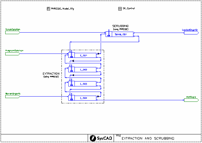
- The uranium is extracted in four extraction stages, each modelled using PHREEQC mixer settler units. Molybdenum is also coextracted. The extent of extraction is determined by PHREEQC thermodynamic calculations.
- The loaded organic is scrubbed using dilute acid. This is again modelled using a PHREEQC mixer settler unit. The aqueous is sent to extraction cell 1 and the scrubbed organic continues on to stripping.
- The scrubbed, loaded organic is stripping using strong acid solution over a series of 7 stripping stages. The extent of stripping is determined by a strong acid stripping isotherm obtained from literature:
- C.A. Morais , L.A. Gomiero , W. Scassiotti Filho , H. Rangel Jr., “Uranium stripping from tertiary amine by sulfuric acid solution and its precipitation as uranium peroxide”, Minerals Engineering, 2005.
- A portion of the stripped organic is washed with water to recover excess acid. The washing process is modelled using a PHREEQC mixer settler unit. The washed organic is then sent to regeneration.
- The washed organic is regenerated with a dilute solution of sodium carbonate to remove all metals from the amine. A PHREEQC side calculation is used to calculate the pH of the spent regeneration solution. The regenerated organic is combined with the portion of the organic which was not washed or regenerated in the barren organic tank.
- Organic diluent and tertiary amine are added to the barren organic tank via makeups. The makeups are controlled as follows:
- Tertiary amine is added to maintain a target percentage amine in the barren organic
- Organic diluent is added so that the flow of barren organic leaving the stripping page exactly matches the flow of organic fed to extraction
- Combined with stream fetch of the extraction organic feed stream, the above is an implementation of a tear on the recirculating organic stream which greatly improves overall model convergence.
Project Configuration
- Most units with reactions are simulated by the PHREEQC mixer settler and mixer settler unit operations.
- Makeup Blocks are used:
- in the Strip Solution Tank to achieve a target acid concentration for feed solution to stripping
- in the Barren Organic Tank to achieve a target amine concentration
- in the Barren Organic Tank to achieve a target product flow
- PID Controllers are used to regulate the addition of sodium carbonate to the regeneration cell (based upon the calculated pH from the PHREEQC side calculation).
- A General Controller is used to perform a number of calculations and to provide an input/output summary for key input parameters and key performance indicators.
- A General controller is also used to calculate the required organic diluent makeup/discard and match the extraction circuit feed flow (to close the organic mass balance).
- PID and SetTag controllers are used to vary the Regen Solution flow (sodium carbonate solution) to the Regeneration Cell to meet the pH target (based upon the calculated pH from the PHREEQC side calculation).
- A PID controller is used to vary the wash water flow to the Wash Cell to produce the required Strip Solution flow to achieve the target advance O:A ratio in the stripping circuit.
Included Excel Report
PHREEQC USX Example Report.xlsx
This file has the following reports:
- Criteria
- Streams
- Mass Balance
Raffinate Water Treatment Example
Project Location
..\SysCADXXX\Examples\05 PHREEQC\PHREEQCFull\Raffinate Treatment Example.spf
Available from Build 139.32067.
Features Demonstrated
- The use of PHREEQC Thermodynamic Calculation Engine.
- The use of PHREEQC Model Configuration.
- The use of PHREEQC Reactor.
- The use of PHREEQC Side Calc Model.
- The use of General Separator.
- The use of Makeup Sources and Makeup Blocks.
- The use of a General Controller.
- The use of a PID Controller.
Brief Project Description
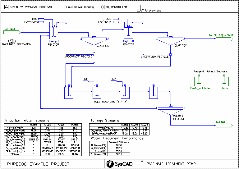
- This is a simplified model of a raffinate water treatment plant. It is a typical plant arrangement with two stage treatment at low and high pH, followed by tailings thickening. It is not intended to model any particular plant.
- The PHREEQC minteq.v4.dat model is used.
- Raffinate wastewater solution is fed to the low pH treatment tank.
- The water is purified in two stages of ferric sulphate and lime addition. The extent of reaction is determined by PHREEQC thermodynamic calculations.
- The tailings are treated in a series of tailings treatment tanks, with the product tailings sent to a thickener.
- The tailings thickener overflow is recycled to the feed of the low pH treatment tank.
- Each clarifier recycles a portion of its underflow back to the tank of its treatment circuit, which is common practice in water treatment to promote better solids settling.
Project Configuration
- Most units with reactions are simulated by the PHREEQC Reactor in constant enthalpy mode.
- Makeup Blocks are used:
- for addition of ferric sulphate (based upon mass ratios for addition)
- for addition of lime slurry
- PID Controllers are used to control the pH of all tanks in the process by the addition of lime
- General Controllers are used to perform a number of calculations and to provide a calculation of removal efficiency for some selected metals.
- Annotation tables are used to report key performance indicators for the plant directly on the flowsheet.
Raffinate Water Treatment Example With Adsorption
Project Location
..\SysCADXXX\Examples\05 PHREEQC\PHREEQCFull\Raffinate Treatment (Adsorption) Example.spf
Available from Build 139.34461.
Features Demonstrated
- The use of PHREEQC Thermodynamic Calculation Engine.
- The use of PHREEQC Model Configuration.
- The use of PHREEQC Reactor.
- The use of PHREEQC Feeder Model.
- The use of General Separator.
- The use of Makeup Sources and Makeup Blocks.
- The use of Discard Sink and Discard Blocks.
- The use of a General Controller.
- The use of a PID Controller.
Brief Project Description
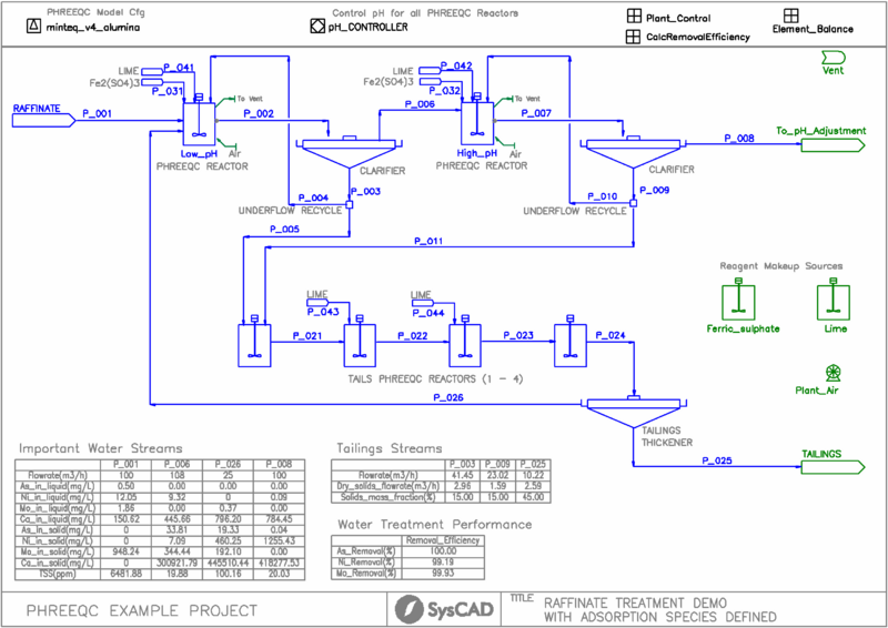
- This is a simplified model of a raffinate water treatment plant. It is a typical plant arrangement with two stage treatment at low and high pH, followed by tailings thickening. It is not intended to model any particular plant.
- This model is very similar to the raffinate water treatment plant example project, but using a different configuration file.
- The PHREEQC minteq.v4.syscad_alumina.dat model is used. It utilizes the minteq.v4 database with additional data on alumina sorption obtained from open literature sources.
- Raffinate wastewater solution is fed to the low pH treatment tank.
- The water is purified in two stages of ferric sulphate, lime and air addition. The extent of reaction is determined by PHREEQC thermodynamic calculations.
- The tailings are treated in a series of tailings treatment tanks, with the product tailings sent to a thickener.
- The tailings thickener overflow is recycled to the feed of the low pH treatment tank.
- Each clarifier recycles a portion of its underflow back to the tank of its treatment circuit, which is common practice in water treatment to promote better solids settling.
Project Configuration
- The Raffinate feed is specified using a PHREEQC Feeder.
- Most units with reactions are simulated by the PHREEQC Reactor in constant enthalpy mode.
- Makeup Blocks are used:
- for addition of ferric sulphate (based upon mole ratios for addition)
- for addition of lime slurry (mass ratios or mass flows set by PID controllers)
- for addition of air (fixed volumetric flow)
- Discard Blocks are used to remove vapours from the pH treatment tank outlets
- PID Controllers are used to control the pH of all tanks in the process by the addition of lime
- General Controllers are used to perform a number of calculations and to provide a calculation of removal efficiency for some selected metals.
- Annotation tables are used to report key performance indicators for the plant directly on the flowsheet.
- The adsorption model in the SysCAD PHREEQC interface is used. This allows calculation of the competitive adsorption of dissolved metals alongside co-precipitation of sparingly soluble salts and metal oxyhydroxides.
- Adsorption extent is determined from the amount of ferric and alumina precipitates generated in the reactions.
- This model was presented at MetPlant 2023. Please request paper for more information.
Included Excel Report
Sensitivity Analysis.xlsm
The file used and its associated macros are described here: Sensitivity Analysis. It has been customised for this project.
