Edit Graphics Commands
Navigation: User Guide ➔ Menu Commands ➔ Graphics ➔ Edit
| Insert | Edit | Delete | Copy & Paste | Display | Animation | Symbol Management | Construct |
|---|
Latest SysCAD Version: 19 March 2024 - SysCAD 9.3 Build 139.35102
Related Links: Graphics for Insert Link and Redraw Link
Introduction
This is a subset of the graphics commands which are used to draw and manage SysCAD flowsheets.
Note: SysCAD must be in the Edit mode (stopped) for most of these commands to be accessed.
Tag Position, Show or Hide
| Command Button | |
| Command Path | Graphics - Edit - Tag Position, Show or Hide |
This command is used to show or hide unit display tags. The scale, rotation and position of the unit tags can be changed using the Update tag annotation dialog box.
There are two parts to this command:
- If the Set tag position option is not ticked, the following dialog box is visible:
- You can show, hide, or change the size or rotation of the tags by clicking on the unit/s of the active Graphics Window.
- The selected unit/s will turn magenta. When you have selected all the required units, either by clicking on them one by one, or using the IWin and CWin buttons to make group selections, press Apply.
- Alternatively, the Show All or Hide All buttons can be used.
- If the Set tag position option is ticked, then following abbreviated dialog box is visible:
- (To see the full dialog box, merely untick the Set tag position option)
- You may reposition the unit tag on the active Graphics Window one at a time.
- Move the mouse cursor over the Graphics Window, the cursor will display UNIT.
- Click on the unit tag you wish to reposition, and the unit will turn magenta and the cursor will now display POS.
- The tag can be moved by either:
- Clicking on a new position for the tag. You can keep positioning the tag by mouse clicks until you are satisfied with the new position.
- The tag can be moved using the arrow keys.
- When you are ready for the next tag, press Next in the dialog box and repeat the above process.
- Press Done when finished.


Note:
You may see a short video on the Editing Tags functionality at Introductory Tutorial - Edit Tag Displays.
Move
| Command Button | |
| Command Path | Graphics - Edit - Move |
Graphics symbols can be moved individually or in a group on the currently active Graphics Window using either:
- Drag and Drop; or
- The graphics can be moved using the arrow keys.
- You may see a short video using the Arrow keys at Introductory Tutorial - Using Arrow Keys to Move, Rotate and Resize Graphical Units.
Move (button or command) opens the following floating toolbar:

- Move the mouse cursor over the active Graphics Window and the cursor will display GRF. Select the entity you want to move by clicking on the unit once if moving a single unit; or draw a box around the units using the
 in-window and
  cross-window buttons. If the selection is incorrect click once away from the selected graphics and try again.
 - Drag and Drop: Pick a point on the selected graphics (for lining up with other symbols, eg, corner of a tank), click on the point and hold down. Use the cross hairs to re-position the graphics symbol. Release the mouse button to complete the move.
- Arrow Keys: Hold down the relevant arrow key to move the selected graphics Up, Down, Left or Right. When the graphics is in the required position, hit the Enter button, or the
 button on the Move dialog box.
 - To move another graphics entity, repeat the above process.
- Press to close the Move Command.
Notes:
- When the graphics symbols are placed/moved manually by the user, they are snapped to small grid.
- To auto snap existing symbols to the big or small grid, click on the symbol(s) to the snapped, then click on either the Large Grid
 or Small Grid
  option from the toolbar, the selected symbol will be "snap" to the nearest grid.
- The graphics can be Moved, Scaled or Rotated using the arrow keys once you have activated either the Scale/Rotate OR Move commands:
- To Move the unit, click on any of the arrow keys to move UP, DOWN, LEFT or RIGHT.
- To Scale the unit, hold down the Control key and click on the UP arrow to increase the scale, or the DOWN arrow to decrease the scale.
- To Rotate the unit, hold down the Control key and click on the LEFT or RIGHT arrow key to rotate left or right.
- To increase the movement or scaling, hold down the Shift key as well, and this will make the changes larger.
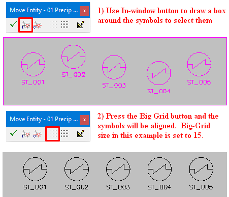
Aligning Models Horizontally or Vertically
To align models horizontally (e.g. row of tanks) or vertically (e.g. Feeders), use the in-window or cross-window button to select multiple units, then press the Big Grid button ![]() . All selected units will be snapped to its nearest grid. This is best used to align multiple units that are just slightly off-alignment.
. All selected units will be snapped to its nearest grid. This is best used to align multiple units that are just slightly off-alignment.
- For Example:
- To change the Grid size, goto Tools|General Options|Graphics Tab (Graphics).
- The redraw button can be used to update the drawing.

Scale/Rotate
| Command Button | |
| Command Path | Graphics - Edit - Scale/Rotate |
Use this button to change the scale and/or rotation for a graphics entity - unit or link on the currently active Graphics Window. It opens the following floating toolbar:

Move the mouse cursor over the active Graphics Window, the cursor will display GRF. Select the entity you want to alter by clicking on the unit once if changing a single unit; or draw a box around the units using the in-window and cross-window buttons. If the selection is incorrect click once away from the selected graphics and try again.
- Graphics can be Moved, Scaled or Rotated using the arrow keys once you have activated either the Scale/Rotate OR Move commands:
- To Move the unit, click on any of the arrow keys to move UP, DOWN, LEFT or RIGHT.
- To Scale the unit, hold down the Control key and click on the UP arrow to increase the scale, or the DOWN arrow to decrease the scale.
- To Rotate the unit, hold down the Control key and click on the LEFT or RIGHT arrow key to rotate left or right.
- To increase the movement or scaling, hold down the Shift key as well, and this will make the changes larger.
- You may see a short video using the Arrow keys at Introductory Tutorial - Using Arrow Keys to Move, Rotate and Resize Graphical Units.
- Click on the Increase Scale or Decrease Scale buttons to change the scale of the selected graphics.
- Likewise, click on the Rotate+ or Rotate- buttons to change the rotation of the graphics entities.
- To use customised scale up factor or rotation angle, use the Dialog button
 . Change the position, scale and rotation of the selected unit as required and press Apply.
 - To accept the change, click Accept or press Restore to retain the original setting.
- To alter another graphics entity, repeat the above process.
- The redraw button can be used to update the drawing.
- Press to close the Scale/Rotate Command.
See the following topics in Frequently Asked Questions:
Change Unit
Please also see ETip: Changing Unit Models
| Command Button | |
| Command Path | Graphics - Edit - Change Unit |
| Short Cut Key | Ctrl+Alt+U |
The actual mathematical model may be changed using this command, without changing the graphic symbol and the links will remain connected. Any unit may be changed to any other type of unit with this command.
Example
For example, the user can change a Shell and Tube Heat Exchanger to a Simple Heat Exchanger by following these steps:
- Click on the 'Change Unit' icon, or go to Graphics - Edit - Change Unit.
- Click on the unit that you wish to change.
- The following dialog box will be visible:
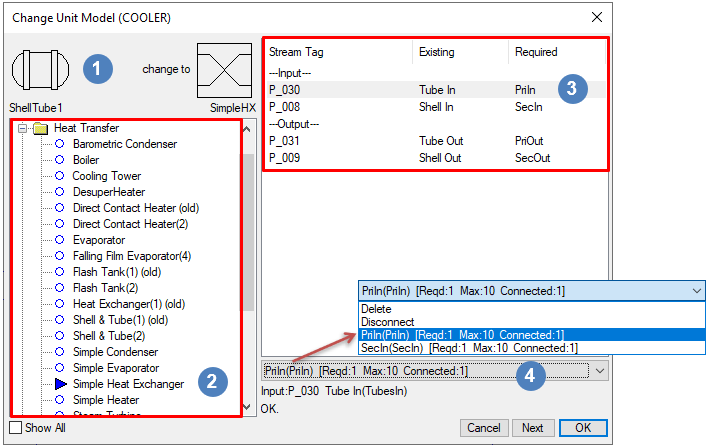
 The default graphics of the existing and new model units will be shown here.
 Select the new mathematical unit model from the list - ANY unit model may be selected.
- Review the link connections and change them, if required.
- To change the link connection, click on the pipe tag
 and then select the required connection from the drop down list
  at the bottom of the dialog box.
- Note that as you select the pipe tag, the pipe is highlighted in the graphics window making it easy to see which pipe is which while checking connections.
- When all of the link connections have been reviewed, click on the 'OK' button.
- When all of the link connections have been reviewed, click on the 'Next' button to change another unit (only available in Build 139 or later). When finished changing units, click the OK button.

Notes:
- The graphical symbol for the model will NOT change. Use the Change Symbol command to achieve this.
- The Left Hand list contains all unit model types available for use in the project.
- To display all unit model types available in the dlls which are loaded, enable the Show All option. This is only available in Build 138 or later.
- If the Include All Unit Models option has been enabled in the cfg file (refer to Model Selection), then all the unit model types are already displayed and this option will be greyed out.
- The user may use this command to change the link connections without changing the actual mathematical model. Ideal for swapping ports of connected pipes.
- The user may change the unit and disconnect one or more links and connect them afterwards to a different unit(s) using the Connect Link or Reroute Link command.
Redraw Link
| Command Button | |
| Command Path | Graphics - Edit - Redraw Link |
| Short Cut Key | Ctrl+Shift+L |
The appearance of the link (including the arrow style and scale size) can be changed using the Redraw link function.
To redraw the link, select the link by clicking on it, this opens the redraw link dialog box, which has the same options as the Insert link dialog box:

|
|
Notes:
- This does NOT change the links connections. If the link connections have to be changed as well, please use Reroute Link
Change Symbol
| Command Button | |
| Command Path | Graphics - Edit - Change Symbol |
| Short Cut Key | Ctrl+Shift+U |
The appearance of the Graphics Symbol for a unit model can be changed using the Change Symbol function. To change unit operation graphics Symbol:
- Select the Change Symbol command
- Observe that the mouse cursor has changed to unit
- Select the unit operation you wish to alter by clicking on it

|
This opens the Change Symbol Dialog box as shown here.
NOTES:
|
Change Text
| Command Button | |
| Command Path | Graphics - Edit - Change Text |
| Short Cut Key | Ctrl+Alt+I |
This command will open the Text dialog box.

- To edit an existing Text string, press Select Next, then change the text and press Apply. You can also reposition the text by selecting a new position. The text is bottom left aligned.
- Once the text is updated, press Select Next to change another string or Done to finish.
- Available from Build 139.34893. User can select a font style from the Font dropdown list to display the text using different fonts.
NOTES:
- This dialog box also servers the Insert Text function.
- To insert new text, click on Create Next, type in the required text in the New Text field, Click on the graphics window to place the text in the required position. The text is bottom left aligned. You can keep clicking to reposition the text to a different position.
- If not text is entered in the New Text field, Text will be the default insert.
- Available from Build 139.34893. The non-standard fonts relies on font shape files located in SysCAD139\Basefiles\Fonts directory. These files differ from the fonts that windows uses to support multiple keyboard/language options. Example text added using Standard Font and Cyrillic font is shown below:

Disconnect Link
| Command Button | |
| Command Path | Graphics - Edit - Disconnect Link |
The user may disconnect either the source or the destination unit, or both, from a link using this command.
For example, we would like to disconnect a pipe that is connected from CCD_1 to CCD_2:
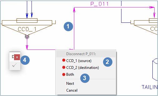
- With the Disconnect Link floating toolbar open, select the link to disconnect, in this case, it is P_011.
- Choose from the popup list which end (source or destination or both) to disconnect from, in this case it is the destination.
- To disconnect another link, simply select another link while the "Disconnect Link" floating toolbar is opened (and cursor displaying "Link"), and repeat. If you do not wish to change the selected link, user can choose
- Next - allows user to ignore the selected link and choose a new link
- Cancel - this will cancel all disconnected link(s) and closes the "Disconnect Link" floating toolbar.
- Click on to finish the Disconnect command.

The link will then turn red and SysCAD will not run until the user reconnects the link, using the 'Connect Link' command, see below.
Note:
- The graphics for the link will NOT change.
- Use Reroute Link which combines "Disconnect", "Connect" and "Redraw" Link into one continuous command.
Connect Link
| Command Button | |
| Command Path | Graphics - Edit - Connect Link |
The user may connect a link to either a source or a destination unit, or both, using this command. The link must have one or both ends disconnected before this command can be used.
For Example: Continued on from the example in Disconnect Link
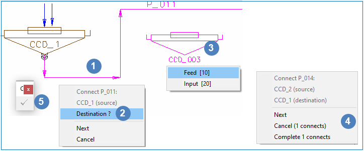
- With the Connect Link floating toolbar open, select the link to connect, in this case it is P_011
- Choose the new unit operation to connect to, in this case it is CCD_003.
- If the new unit operation has more than one connection, choose from the popup list which IO to connect to. When connect link is complete, the cursor should display "Link".
- To connect another link, simply select another link while the "Connect Link" floating toolbar is opened (and cursor displaying "Link"), and repeat. If you do not wish to change the selected link, user can choose
- Next - allows user to ignore the selected link and choose a new link
- Cancel ("number" connects) - this will cancel all connected link(s) and closes the "Connect Link" floating toolbar.
- complete "number" connects - this will complete all connected link(s) and closes the "Connect Link" floating toolbar.
 Click on to finish the Connect command.

Note:
- The graphics for the link will NOT change.
- Use Reroute Link which combines "Disconnect", "Connect" and "Redraw" Link into one continuous command.
Reroute Link
| Command Button | |
| Command Path | Graphic - Edit - Reroute Link |
Only available in Build 139 or later.
This command is a combination of the Disconnect Link, Connect Link and Redraw Link commands. This allows the user to reroute the link by automatically activating Disconnect and/or Connect link and Redraw Link commands.
Click on a link to reroute,
|

|
 |
|
 |
|
 |
NOTES:
|
Create Group
| Command Button |
This command allows the user to choose selected groups of SysCAD models and save them in a text file. Once the group of models is saved, they can be inserted onto any graphics windows, this includes different projects. This is an easy way to create multiple flowsheets that contain the same layout of models. This functionality works in a similar way to the Copy and Paste Graphics Commands.
To create a group:
- Open a project that contains a graphics page with the required models for copying
- Use the 'Copy' command, or enter Ctrl+C to bring up the 'Copy to Clipboard' floating toolbar, this includes the 'Create Group' button:
- Select the required models one at a time by LEFT clicking on them or use the cross-window or in-window buttons on the Copy to Clipboard tool bar.
- When all the models have been selected, press the Create Group button to bring up the Create Group dialog box:
- Enter a name for the new group and a description if desired. Any previously defined groups will be shown in the list under the name field.
- Press the OK button to save the model information in a text file in the CfgFiles\Groups folder.


Once the group has been created, it can be inserted into a project using the Insert Group command.