Setting up Transfer Pull Network
Navigation: User Guide ➔ Solver ➔ Simulation Modes ➔ Dynamic Transfer ➔ Setting up Transfer Pull Network
Related Links: Dynamic Transfer - Transfer Pull Mode
Selecting Transfer Pull Mode
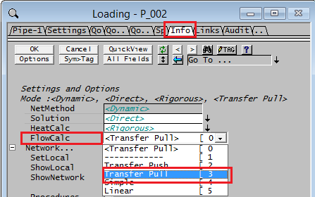
- To use Transfer Pull mode for a small portion of the project (with the majority of the project being Transfer Push), right click on any Pipe/Valve-1/Pump-1 to be included Transfer Pull Local network, change the FlowCalc method to Transfer Pull (located on the Info Tab).
- SysCAD will analyse all the surrounding units to establish the flow network.
- Flow network will begin from Feeder or Surge Exit and end with Output or Surge unit entry.
View and Manage Local Network
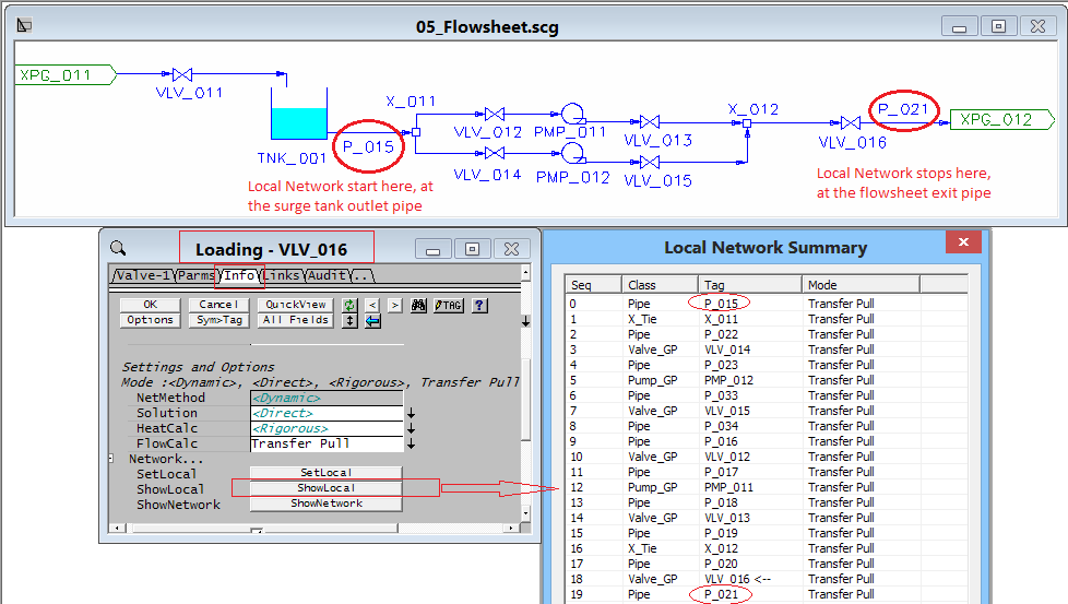
To view all the process units in a local Transfer Pull Network, right click on any unit in the network to bring up the Access Window, on the Info Tab, under the Network... Section, select the ShowLocal button to open the Show Local Summary Window. Example is shown below:
Notice the Feed to the tank does not belong to this local network, the flow supply to the network comes from the content of the Tank and not the feed to the tank.
Once the local network is formed, it will stay as a network until changes are made, these may include:
- adding/deleting equipment within the network
- connecting the output feeder with another part of the process (using cross page connection)
- Changing the process unit type using Change Model
If changes are made, local network will need to be re-established. To do this, simply press the SetLocal button (as shown in the bitmap above).
Simple Transfer Pull Network Examples
Process Units that will form part of the Transfer Pull local Network include Feeder/XPG-1 (used as cross page Connector), Tie, Pump-1, Valve-1. Process units that will break the Transfer Pull Local Network include Feeder/XPG-1 (NOT used as cross page connector), Surge unit such as Tank.
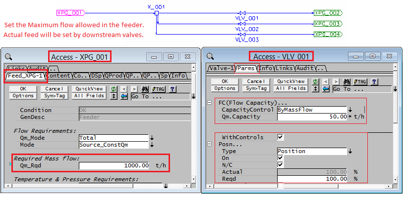
Example 1: Transfer Pull Network with Single Feed Source and Multiple Valves
In this example, the flow can be set up in two ways:
- Define flow capacity in all the valves, define the maximum flow allowed into the network in the feeder. The actual flow into the flow network will be calculated based on the valve settings (valve open/close, opening position). If the Maximum flow set in the feeder is less than total valve demand, then flow to each valve will be reduced proportionally.
- Define the Actual flowrate in the Feeder; Set some/all the Valve CapacityControl to Off, the full flow will be distributed between all the valves that are turned on.
- Viewing Transfer Pull Results
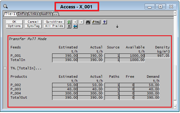
The best place to obtain flow network information is from Ties (where flow split or combine), as shown in the picture below.
We can obtain the following information from this summary:
- The Maximum available flow allowed is 1000 t/h (user defined value, set in the feeder)
- The actual flow to the network is 390 t/h, which is the sum of P_002 (set by Valve_1), P_003(set by Valve_2) and P_004 (set by Valve_3)
- The flow network has 3 flow paths (from the tie)
Example 2: Transfer Pull Network with Flow Restriction
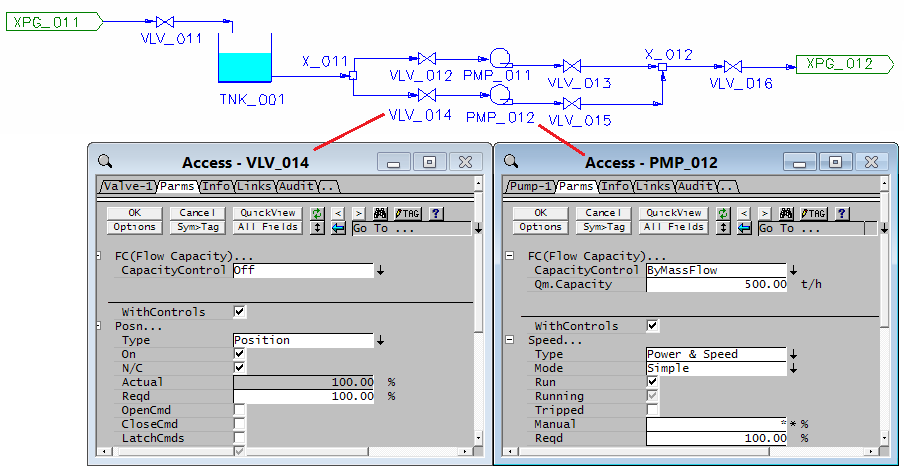
- In this example, user must specify flow capacity for both pumps.
- Pump speed can be used to vary the pump throughput.
- Pump can be stopped to block flow.
- Valves VLV_012, to VLV_015 maybe left as ON/OFF valves (with no flow capacity configured). Use these valves to isolate flow if required.
- Valve VLV_016 maybe used to restrict flow from the flow network.
- If TNK_001 has enough material, and isolation valves (VLV_012 to VLV_015) are opened, then flow out from TNK_001 will be the lower value of (PMP_011 * %Speed/100 + PMP_012 * %Speed/100) and (VLV_016 * %Opening/100).
Example 3: Transfer Pull Network with Multiple Feed Sources
In this example,
- The valve capacity control maybe set to the Off position, as flow demand should come from the pump.
- If a capacity is set for the valve, then the lower of the two capacities (valve or pump) will be used for the network.
- User MUST specify flow capacity for the pumps.
- The pump/valve maybe switched off.
- The actual flow may be varied by varying the pump speed.
Multiple Source Issue:
- This project has more than one source (XPG_005 and XPG_006), this is generally NOT recommended as there is no definite solution as to how the total feed is supplied.
- A better way of configuring this flowsheet is to add a valve to one of the feeding lines, thus allowing one line to float only.
Example 4: Working around the No Recycle Permitted Issue
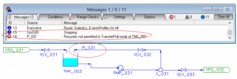
SysCAD in Transfer Pull Mode does not currently support a recycle within an identified local Transfer Pull Network. The error message as shown below is given and the solver will not proceed.
In this example, part of the flow is returned to the tank, creating a recycle loop, this is not allowed in the Transfer Pull Mode. In some recycle arrangements there could be an infinite number of solutions. To workaround this issue, and still use Transfer Pull mode, the following modification is needed:
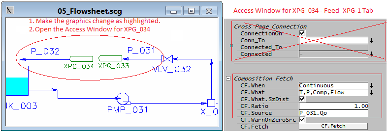
- Break up line P_031 with two feeder/XPG connectors
- Do NOT use the cross page connection to link up the flow, as this actual will cause the two pipes to be treated as one.
- Use the Composition Fetch section to transfer all flow properties from P_031 to XPG_034. The Composition Fetch makes an exact copy of the flow conditions while keeping the line "broken", thus breaking the recycle line.
Notes:
- By breaking the recycle with crosspage connectors and using composition fetch, an iteration delay is introduced. At any given step, the flow in pipe P_032 will be equal to the flow in P_031 from the previous step. Care may be required in setting the flow in XPG_034 for the very first iteration.
