Controls Window
Navigation: User Guide ➔ Windows ➔ Controls Window
| Application Window | Message Window | Graphics Window | Access Window | Explorer Window | Trend Window | Controls Window | TagList Window | Project Window |
|---|
Latest SysCAD Version: 19 March 2024 - SysCAD 9.3 Build 139.35102
Related Links: Control Commands, Controls
Introduction
The main functions of this Controls Window are to list all the PID controllers used in the project for analysis, trending and tuning. It is The Controls window is saved with extension trc. From Build 139, this file is saved to the \DocsTrend subfolder.
When a new Controls page is created, all PID controllers used in the project will be added to this Controls window automatically. From Build 139.31866, the list of PIDs is automatically sorted and updated as PIDs are added, deleted or renamed. In older Builds, this needs to be done manually by using the Trend | Reconnect all option.
Open a New Controls Window
To open a new Controls window, use one of the following commands:
- If the 'Control' menu is active (click on any Controls window), click on Control - New Control Window.
- Right click on 'Trends' in the Explorer Window (if this is not already open, click on View - Explorer) and select 'New Controls Window'.
- With a project open, use one of the following commands:
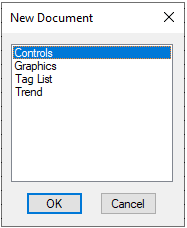
- Window - New Document
- Icon:

- Short Cut Key: Ctrl+N
- Select the 'Controls' option, and press 'OK'.
Each of these methods will open a new Controls Window 'Controls_x.trc.'
Notes:
- This command is only available if a SysCAD project is open.
- This command is not available if SysCAD is solving or running.

The Tuning Parameters
The controls window is basically divided into three sections, the first and third sections are the same as the normal trend window, being the Trend Line View and Trend List View respectively. See Trend Window (Normal). The second section is unique to the controls window, listing all the necessary tuning parameters for the controllers.
An example of the Controls window is shown below:

Notes on Autotune:
- Only one PID loop can be auto tuned at any one time. The user may then repeat the exercise to tune other controllers in the project.
- As with any operating plants, some controllers may need more fine tuning depending on the interaction with other controllers. In most cases, it is best to hand-tune some of the more sensitive controllers first to get the plant under control and use the auto tune for optimisation.
| Tuning Options |
|
| Plant Value |
|
Turning PID Values and Tuning Parameters |
|
Turning triggers and status display |
|
| Trending |
|
How to Auto Tune a Single Loop
- Add a Controls Window if the project doesn't already have one. (One per project only.)
- Enable the AutoTune
 option which is located at in the top left corner of the Controls Window
 - Make sure all PID controllers have the TuneWithHold
 option selected
 - If the controller to be tuned is currently converged, force it to change output by either introducing a disturbance/step change to a variable which will affect its measured value or simply change the controller's setpoint
- For the PID controller to be tuned, left click on the relevant
 under the State heading
  , if the
  is not present, right click under the State Heading next to the PID of interest and choose Tune.
 - Solve or Run the project
 , this will start the PID tuning
 - All the other controller's outputs will be held constant while the controller is being tuned, shown by the symbol


- While the controller is being tuned, the
 &
&  symbols will be shown next to it and the controller output will be held constant
 - When the tuning has been completed, the controller settings (Gain, Integral, Derivative) will be changed to new values and all controllers will be allowed to control normally
