Shell and Tube Heat Exchanger 2
Navigation: Models ➔ Energy Transfer Models ➔ Shell and Tube Heat Exchanger 2
| Flash Tank | Evaporator | Falling Film Evaporator | Shell&Tube Heat Exchanger | Simple Heat Exchanger | Barometric Condenser | Direct Contact Heater | Simple Heater | Simple Evaporator | Simple Condenser |
|---|
General Description
The Shell and Tube Heat Exchanger 2 is used to transfer energy from one stream to another. It is primarily used to transfer latent heat from a condensing vapour stream, currently only steam, to a liquor stream. The liquor stream may contain liquids and solids. The unit may also be used for sensible heat exchange between two fluids without any phase changes.
There are several operational modes combination for the Shell and Tube Heat Exchanger 2. See Selecting Operating Methods for Shell and Tube 2.
If the heat exchanger is inserted as part of a Flash Train, see Flash Train for a description of the theory and variables. This documentation will only discuss the variables for a 'standalone' heat exchanger.
An Environmental Heat Loss may be included in the unit under some operating modes, see the above table. This allows the user to specify a heat loss, or gain, between the unit and the environment.
A key difference with the Shell and Tube Heat Exchanger is that a Reaction Block (RB) can be included on the tube side. Please do be aware that only Reactions are recognised in this unit. Any Source, Sink or HX in the reaction file will be IGNORED.
Diagram

The diagram shows the default drawing of the shell and tube heat exchanger 2, with the required connecting streams. The user may also connect a vent stream to the unit. This is optional and allows non-condensable and excess steam to be removed from the unit.
The physical location of the connections is not important; the user may connect the streams to any position on the drawing. When the user inserts a heat exchanger into a flowsheet, he may choose a different drawing from a pull down menu.
Inputs and Outputs
| Label | Required Optional |
Input Output |
Number of Connections | Description | |
| Min | Max | ||||
| Tube_In | 1 Required | In | 1 | 10 | The liquid or slurry feed to the unit. Reactions are allowed in the Tube side. |
| Tube_Out | Required | Out | 1 | 1 | The liquid or slurry outlet. |
| Shell_In | 1 Required | In | 1 | 10 | The steam inlet in condensing mode. When using "sensible HX mode with EnironHX", this should be the hot in. |
| Shell_Out | Required | Out | 1 | 1 | The condensate out in condensing mode. When using "sensible HX mode with EnironHX", this should be the hot out. |
| Vent | Optional | Out | 0 | 1 | Optional shell side vent for non-condensable and excess steam. |
Note: Incoming streams to the same connection label are perfectly mixed before any unit operations are performed.
Behaviour when Model is OFF
If the user disables the unit, by un-ticking the On tick box, then the following actions occur:
- All streams connected to the 'Shell' inlet will flow out of the 'Shell' outlet with no temperature or phase change;
- All streams connected to the 'Tube' inlet will flow out of the 'Tube' outlet with no temperature or phase change;
- Any sub-models, such as Reaction Block, will not occur;
- No energy exchange will occur.
So basically, the unit will be 'bypassed' without the user having to change any connections.
Model Theory
General Theory
The unit is based on traditional heat exchanger theory1,
- [math]\displaystyle{ \mathbf{\mathit{Q=UA\boldsymbol{\Delta}T_{LM}}} }[/math]
- where
- Q - Rate of Heat Transfer
- U - Overall coefficient of Heat Transfer
- A - Area available for Heat Transfer
- [math]\displaystyle{ \mathbf{\mathit{\boldsymbol{\Delta}T_{LM} = \cfrac{\Delta T_2 -\Delta T_1}{\ln \left( \cfrac{\Delta T_2}{\Delta T_1} \right) }}} }[/math] - Log Mean Temperature Difference (LMTD)
- For Counter Current Flow [math]\displaystyle{ \; \Delta T_2 = T_{H_{in}} - T_{C_{out}} \quad }[/math] and [math]\displaystyle{ \; \Delta T_1 = T_{H_{out}} - T_{C_{in}} }[/math]
Notes:
- If the flow through the heat exchanger is not completely counter current, then user must input a LMTD correction factor to correct for the different flow configuration. These correction factors are available in most references on Heat Transfer theory, and should be available from specific heat exchanger suppliers.
- If the heat exchanger has Superheated Steam condensing on the shell side, then the LMTD method will produce small inaccuracies, please see Log Mean Temperature Difference (LMTD) Discussion.
Heat transfer to the individual streams is calculated using the following equation:
- [math]\displaystyle{ \mathbf{\mathit{Q=m(H_{in}-H_{out})}} }[/math]
- where
- Q - Rate of Heat Transfer
- m - Mass flow of the stream
- Hin - Enthalpy of entering stream
- Hout - Enthalpy of leaving stream
Using the stream enthalpies in the heat transfer calculations ensures that the variation of specific heat with temperature is taken into consideration.
In the case of one of the streams condensing the heat transfer is based on the assumption that the vapour is condensed at the saturation temperature. The condensate leaves the unit at this temperature, i.e. there is no further cooling of the liquid. If the vapour enters the unit above the saturation temperature, it will be cooled to the saturation temperature and then condensed.
The unit uses an iterative technique to determine the LMTD of the unit. This is then used to calculate the heat transfer between the two streams.
Reference
- Perry, R.H., Perry's Chemical Engineers' Handbook, McGraw Hill Inc, 6th Edition, 1984.
Method: Sensible HX
- The Sensible HX operating mode allows user to enter a value for environment heat loss. To make sure he heat loss is applied correctly to the hot side, the hot stream must be connected to the Shell side.
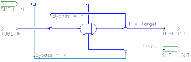
- Bypassing and Temperature control (Available from Build 139.)
- While in sensible heat model, user can set a portion of the shell or tube feed to bypass the heat transfer calculations. User can also select the bypass control to adjust the bypass fraction to meet the outlet shell/tube temperature requirements.
- The bypass flow can be visualised as:

Method: Condensing
- Steam must be connected to the Shell side.
- Autoclave Option
- Selecting the Autoclave option: Calculates MTD based on difference between condensing temperature and primary (tube) outlet temperature. This simulates a fully mixed autoclave with internal steam heating. The advantage of this over the present Tank heat exchange element is that it can be act as part of a Flash Train.
- The Autoclave option is available for Condensing and Live Steam operations. Note that in Live Steam operation, area is ignored, all available steam will be condensed to the the limit where the incoming primary stream is heated to the steam condensing temperature. Steam flow should be controlled externally in this case.
- Including Reactions
- Selecting the Use.RMTD option: (Reactive Mean Temperature Difference). If there are significant reactions along a heat exchanger section, then the temperature profile may be different to that used in calculation LMTD (Log Mean Temperature Difference). The effective mean temperature difference is also different, though in most cases only by a small percentage. Though for example, if very large amounts of heat were generated by reactions, the heat transfer direction could even reverse.
- The RMTD option implements an alternative calculation of MTD, accounting for the reaction heat. In some cases (the example just given) this may give numerical errors. Use the LMTD in that case. If the LMTD and RMTD are dramatically different, this is an indication that the reactions have a significant influence on overall heat transfer.
- NOTE: The Shell and Tube 2 unit will IGNORE any Source, Sink or Heat Exchange in the Reaction file. Only Reactions will be recognised.
- General Demand
- If the Condensing Method is Demand (UA), then the model will condense (and hence demand) sufficient steam at the feed saturation conditions to satisfy the LMTD equation.
- Add in Tube Out Temperature Constraint
- Selecting the Condensing Method to be Demand (UA & Tube T) adds in one extra constraint - the tube outlet temperature. This means the process must have one more variable to change to balance the flowsheet, and this variable is the steam pressure.
Internally, the working of the model can be visualised as: 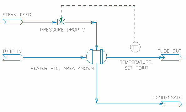
The steam line pressure drop is shown in the model as Shell.dP and the Tube outlet Temperature setpoint is entered as RequiredTubeT.
This method will work out the amount of steam needed based on the UA of the heater, and the pressure drop required will be determined by the tube out temperature. When using this method, user must be certain of the heater configuration and temperature out requirements, as a solution may not be possible if for example the vapour temperature is too low.
- Note the difference with the Demand (UA) method - in that case there is no control on the steam flow, and hence the tube outlet temperature is unconstrained.
- The Demand methods work with multiple steam feeds. In this case, there must be a single' supply connected to a demand source, the others receiving fixed flows. If the fixed flows are inadequate to meet the demand requirement, the demand flow will be adjusted to make up the difference. If the fixed flows are greater than needed to meet demand, then excess flow will be vented or passed to the condensate outlet.
- Multiple feeds at different pressures are physically unrealistic and care should be taken in this case. All the feeds will be combined at the demand feed pressure - with the saturation temperature being that of the demand supply. This may give misleading results if there is excess flow from the fixed supplies and they are at different pressures to the demand supply.

- Configuration Limits
- To avoid temperature cross over issues:
- Slurry out Temperature is limited to be <= Condensate out temperature.
- When using the Demand (UA & TubeT) method, the Shell Pressure drop will be limited by the condensate out temperature, as this temperature cannot be lower than the user defined Tube.TemperatureReqd.
- UA is currently limited to 10,000 kW/K. If a larger value is needed, use multiple exchangers in series or parallel as appropriate - this will give a better overall representation of large heat transfer models.
- The Shell and Tube 2 unit will IGNORE any Source, Sink or HX in the reaction file - e.g. if a reaction file with a source is loaded, the source will be ignored and any reactions which have the source species in them will not occur.
- Vent Mass flow limit allows the user to limit the maximum flow as a percentage of the steam entering the HX. This allows at least some steam to be used for condensing.
- Tube side flow limit: if tube side flow is below this limit, the HX is considered to be inoperative.
- Heat loss limit allows the user to define the maximum heat loss as a percent of condenser duty.
Method: Evaporating
Available from Build 139.
The cold fluid is connected to the Shell and the hot fluid to the Tube side. The Hot fluid will provide the energy for the evaporation of the cold fluid.
The amount of evaporation could be limited by feed conditions and/or heater configurations (such as HTC and area). Possible outcomes are:
- No Evaporation: The Shell fluid is heated to a temperature below its saturation temperature. (If energy available is less than energy required for evaporation)
- Partial Evaporation: The flash species is partially vaporised at its saturation temperature. (If energy available is less than energy required for Complete evaporation)
- Complete Evaporation: The flash species is completely vaporised and subsequently superheated. (If energy available is greater than energy required for Complete evaporation)
- Forced Evaporate All: If the "EvaporateAll" tickbox is ticked, The flash species is completely vaporised while ignoring the area provided, the shell out temperature will be at the saturation temperature.
- Note that this mode could return an energy balance error where if energy required for Complete evaporation is greater than energy available.
- Assumptions
- The Heat Transfer Coefficient is constant; in particular it is not a function of the vapour fraction in the fluid being vaporised.
- Heat transfer in the Heat Exchanger is defined by the LMTD equation regardless of the phase composition of the fluid being vaporised.
- There is no phase change in the hot fluid which supplies energy for the vaporisation.
- If the fluid is partially vaporised, its final temperature is the saturation temperature of the remaining liquid .
- The Heat Exchanger will not operate as a Condenser (notwithstanding that this may be physically possible).
Selecting Operating Methods for Shell and Tube 2
| Method | Condensing Method | Demand Connection | Autoclave | Reactions | EnvironHX | Vent | Description | |
|---|---|---|---|---|---|---|---|---|
| 1 | Sensible HX | N/A | allowed | allowed | allowed | Used for simple heat exchange operations between the two sides, with no phase change. The hot side can be connected to either tube or shell. Flow demand network is allowed to pass through on the tube side only. | ||
| 2 | Condensing | No Demand Calc | allowed | allowed | allowed | allowed | Steam supply to be specified by the user, unit will condense all the steam to water, Maximum Tube out temperature is limited to be the same as steam feed temperature. If excess amount is supplied, unit will return a warning for possible energy imbalance. | |
| 3 | Demand (UA) | None (manual) | allowed | allowed | allowed | allowed | Steam supply to be specified by the user, unit will condense steam to water based on the Heater UA (HTC and Area) supplied. Maximum Tube out temperature is limited to be the same as steam feed temperature. If excess amount is supplied, unit will return a warning.
With this configuration, the steam supply must be correctly specified by the user, normally via a General Controller or Set Tag Controller. This is easily implemented as the steam flow required is calculated and displayed as tag VapourFlow.Rqd. | |
| 4 | FlashTrain | allowed | allowed | allowed | allowed | Steam supply to be connected to Flash Tank Vapour outlet, the unit will demand steam from the flash tank based the Heater UA (HTC and Area) supplied. All steam is condensed to water. | ||
| 5 | General Demand | allowed | allowed | allowed | allowed | Steam supply is connected directed or indirectly to a Feeder (with Demand.On selected), unit will demand and condense steam to water based on the Heater UA (HTC and Area) supplied. If excess amount is supplied (minimum in feeder too high), unit will return a warning. The Demand (UA) models are essentially uncontrolled, the tube outlet temperature being determined by the area and heat transfer coefficient | ||
| 6 | Demand (UA& TubeT) | None (manual) | N/A | N/A | N/A | N/A | Steam supply to be specified by the user, unit will condense all the supplied steam to water. The user also defines the required Tube out temperature, this sets the maximum tube out temperature. The variable in this configuration is the steam feed pressure, if too much steam is supplied, the unit will attempt to drop the pressure of the steam to balance all the specified constraints. If a balance is not found, warnings are given. The minimum shell out temperature (achieved by pressure drop) is limited to the tube out temperature. This method also assumes the user know the exact size of the heater.
With this configuration, the steam supply must be correctly specified by the user, normally via a General Controller or Set Tag Controller. This is easily implemented as the steam flow required is calculated and displayed as tag VapourFlow.Rqd. | |
| 7 | FlashTrain | N/A | N/A | N/A | N/A | Steam supply to be connected to Flash Tank Vapour outlet, the unit will demand steam from the flash tank based the Heater UA and tube outlet temperature supplied. All steam is condensed to water. If the heater area is too big to give the required tube out temperature, the steam pressure is dropped to attempt to achieve a balance. The minimum shell out temperature (achieved by pressure drop) is limited to the tube out temperature. The maximum tube out temperature is limited by the user specified tube out temperature. | ||
| 8 | General Demand | N/A | N/A | N/A | N/A | Steam supply is connected directed or indirectly to a Feeder (with Demand.On selected), unit will demand and condense steam to water based on the Heater UA and Tube out Temperature supplied. If excess amount is supplied (minimum in feeder too high), unit will return a warning. All steam is condensed to water. If the heater area is too big to give the required tube out temperature, the steam pressure is dropped to attempt to achieve a balance. The minimum shell out temperature (achieved by pressure drop) is limited to the tube out temperature. The maximum tube out temperature is limited by the user specified tube out temperature. Compared to the Demand (UA) configuration, this mode controls (by dropping) the steam pressure to achieve the desired outlet temperature | ||
| 9 | Evaporating | N/A | N/A | N/A | N/A | Available from Build 139. Shell side stream can be evaporated. Hot stream expected to be on tube side. |
Data Sections
The default access window consists of several sections:
- ShellTube2 tab - This first tab contains general information relating to the unit.
- QTubeIn - Optional tab, only visible if ShowQTubeIn is enabled. This page shows the properties of the mixed stream as the feed to the Tube side.
- QShellIn - Optional tab, only visible if ShowQShellIn is enabled. This page shows the properties of the mixed stream as the feed to the Shell side.
- VLE - Only visible if the unit is in either Condensing or Evaporating mode.
- RB - Optional tab, only visible if the Reactions are enabled. Please note that the Shell and Tube 2 unit will IGNORE any Source, Sink or HX in the reaction file.
- ShellSide - Optional tab, only visible if the user selects Tube Detail for the layout.
- TubeSide - Optional tab, only visible if the user selects Tube Detail for the layout.
- Info tab - Contains general settings for the unit and allows the user to include documentation about the unit and create Hyperlinks to external documents.
- Links tab, contains a summary table for all the input and output streams.
- Audit tab - Contains summary information required for Mass and Energy balance. See Model Examples for enthalpy calculation Examples.
Shell and Tube Heat Exchanger 2 Page
Unit Type: ShellTube2 - The first tab page in the access window will have this name.
| Tag (Long/Short) | Input / Calc | Description/Calculated Variables / Options |
| Tag | Display | This name tag may be modified with the change tag option. |
| Condition | Display | OK if no errors/warnings, otherwise lists errors/warnings. |
| ConditionCount | Display | The current number of errors/warnings. If condition is OK, returns 0. |
| GeneralDescription / GenDesc | Display | This is an automatically generated description for the unit. If the user has entered text in the 'EqpDesc' field on the Info tab (see below), this will be displayed here. If this field is blank, then SysCAD will display the UnitType or SubClass. |
Requirements | ||
| On | Tick Box | Switches the Heat Exchanger on/off |
| Method | Sensible HX | This will allow sensible heat exchange between two streams. No phase change will take place automatically. Please see Selecting Operating Methods for Shell and Tube 2 |
| Condensing | This is used to condense the steam. Steam must be connected to Shell In. Please see Selecting Operating Methods for Shell and Tube 2 | |
| Evaporating | Available from Build 139. This is used to evaporate a stream, usually water. The stream to be evaporated must be connected to Shell In while the hotter stream must be connected to Tube In. | |
| (Bypass functionality is only available from Build 139.) | ||
| Bypass.Option (Only visible if Method is set to Sensible HX) |
No Bypass | Full Tube and shell flows will be used for heat transfer calculations. |
| Bypass Shell Feed | user can specify a portion of the shell feed to bypass the heat transfer calculations, this is equivalent to adding a split to the shell feed, the bypassed amount will be added to the shell out stream. | |
| Bypass Tube Feed | user can specify a portion of the tube feed to bypass the heat transfer calculations, this is equivalent to adding a split to the tube feed, the bypassed amount will be added to the tube out stream. | |
| Bypass.Control (Only visible if Bypass.Option is set to Bypass Shell Feed or Bypass Tube Feed) |
Fixed Fraction | user can specify a fixed portion of the shell/tube feed to bypass the heat transfer calculations. |
| Shell Outlet T | the portion of the shell/tube feed to bypass the heat transfer calculations is adjusted to meet the user defined shell outlet temperature. | |
| Tube Outlet T | the portion of the shell/tube feed to bypass the heat transfer calculations is adjusted to meet the user defined tube outlet temperature. | |
| Bypass.FracReqd | Input | Only displayed if Bypass.Control = Fixed Fraction. |
| Bypass.T_Reqd | Input | Only displayed if Bypass.Control is set to Shell Outlet T or Tube Outlet T. |
| Bypass.FracMax | Input | Only displayed if Bypass.Option is set to Bypass Shell Feed or Bypass Tube Feed. |
| CondensingMethod (Only visible if Method is set to Condensing) |
No Demand Calc | The Steam addition is manually specified by the user, all steam supplied (less vent) will be condensed. Duty will be based on Tot.Cond.Duty (total condensing duty). NOTE: Duty may not equal to TheoreticalDuty (calculated from HX UA and LMTD) as steam input is manual. Please see Selecting Operating Methods for Shell and Tube 2 |
| Demand (UA) | The steam demand is calculated base on the user specified Heater HTC and Area (UA). Please see Selecting Operating Methods for Shell and Tube 2 | |
| Demand (UA&TubeT) | The steam demand is calculated base on the user specified Heater HTC, Area and the tube outlet temperature. Please see Selecting Operating Methods for Shell and Tube 2 | |
| DemandConnection (Only visible if CondensingMethod is set to one of the Demand methods) |
None (Manual) | Please see Selecting Operating Methods for Shell and Tube 2 |
| FlashTrain | The steam supply comes from a Flash Tank and the Flash Tank - Heater is in a Flash train mode. Please see Selecting Operating Methods for Shell and Tube 2 | |
| GeneralDemand | The steam supply comes from (directly or indirectly) a Feeder with Demand.on selected. Please see Selecting Operating Methods for Shell and Tube 2 | |
| Tube.TemperatureReqd / Tube.T_Reqd | Input | Only visible if the CondensingMethod is set to Demand (UA & Tube T). User specified Tube out Temperature. This is also the maximum Temperature for the Tube outlet stream. |
| Reactions | List box | Switches the Reactions on/off. Reactions occur on the tube side only and the Shell and Tube 2 unit IGNORES any Source, Sink or HX in the reaction file. |
| ShellSide.On | Tick Box | Only visible if Condensing Method is set to No demand calc or Demand (UA). |
| Autoclave | Tick Box | Only visible if Method = Condensing. If this is enabled the unit will use temperature difference rather than LMTD in heater calculations. Calculates MTD based on difference between condensing temperature and primary (tube) outlet temperature. This simulates a fully mixed autoclave with internal steam heating. |
| Use.RMTD | Tick Box | Only visible if Reactions are 'On' and Condensing Method = Demand (UA). This enables an alternative calculation of MTD, accounting for the reaction heat. See theory above. |
| IgnoreSteamFlow | Tick Box | This is only available if CondensingMethod = Demand (UA). Adjust steam feed rate to match duty and report excess or low flow conditions. When the flash train model has converged correctly, the steam flow rate will be matched and an error is not reported. Note: If this option is enabled and
|
| Flow.Damping | Input | This is only available if CondensingMethod = Demand (UA). In solving macro models, there may be situations when the solver overshoots and fails to converge. This is because the demand from the model is interacting with supply from Flash Tanks. If the unit model steam flow and pressure seems to be oscillating about, then put in a value of 0.8 for the flow damping. This will stabilize the oscillations and allow the model to converge. It will slow the overall convergence rate if used when unnecessary, so only turn this on (change the default value of 0.0) if flash trains are not converging. |
| EnvironHX | Tick Box | Switches the environmental heat exchanger sub model on/off, used for additional heat losses. This is NOT available if CondensingMethod = Demand (UA & TubeT). |
| Env.Model | Only available if EnvironHX has been selected. For EnvironHX to perform correctly, the HOT stream must be connected to the Shell side. | |
| None | No environmental heat loss. | |
| FixedHeatFlow | Fixed Environmental heat loss for the unit operation. | |
| Env.HeatFlowReqd | Input/Calc | Only shown if EnvironHX has been enabled. The amount of heat lost to the environment. |
| Env.MaxLossFrac | Input/Calc | Only shown if EnvironHX has been enabled. The maximum fraction of heat lost to the environment as a percent of HX duty. |
| Layout | Overall | User specifies the overall heater area and HTC |
| TubeDetail | User can specify the tube side in more detail. Refer to the Tubeside Tab for details. | |
| HTC | Input/Calc | If the Overall method is selected then this field allows the user to specify the heat transfer coefficient. If the TubeDetail method is selected then this field shows the calculated heat transfer coefficient (the HTC is specified on the ShellSide/TubeSide tabs). |
| Area | Input/Calc | If the Overall method is selected then this field allows the user to specify the heat transfer area. If the TubeDetail method is selected then this field shows the calculated heat transfer area (based on user specified information on the TubeSide tab). |
| LMTDFact | Input | User specified LMTD factor |
| VentMassFlowReqd | Input | Only available if CondensingMethod = No demand calc or Demand (UA). User specified amount of steam to be vented (This could be limited based on steam available) |
| Vent.MassFracOfFeed | Input | Only available if CondensingMethod = No demand calc or Demand (UA). User specified maximum fraction of steam to be vented based on feed steam to the HX. |
| Tube.LowQmLimit | Input | User specified minimum tube side flow, if flow is lower than the limit, then the HX is considered to be inoperative. |
| EvaporateAll | Tick Box | Available from Build 139. Only displayed if Method = Evaporating. All of the VLE species in the shell side stream will be evaporated, i.e. evaporation will not be limited by area. |
| Options | ||
| ShowQTubeIn | Tick Box | QTubeIn and associated tab pages (e.g. Sp) will become visible, showing the properties of the combined Tube feed stream. See Material Flow Section. This will be prior to any sub-model actions (e.g. Reactions). |
| ShowQShellIn | Tick Box | QShellIn and associated tab pages (e.g. Sp) will become visible, showing the properties of the combined Shell feed stream. See Material Flow Section. This will be prior to any sub-model actions. |
| ShowQTubeOut | Tick Box | QTubeOut and associated tab pages (e.g. Sp) will become visible, showing the properties of the combined Tube side outlet stream. See Material Flow Section. |
| ShowQShellOut | Tick Box | QShellOut and associated tab pages (e.g. Sp) will become visible, showing the properties of the combined Shell side outlet stream. See Material Flow Section. |
| TrackShellFlowWhenOff | Tick Box | Only used when model is Off. Gives a warning condition when the model is off and there is shell side feed. For the Condensing Method with FlashTrain DemandConnection then this warning is always given when the model is off and there is shell side feed flow. Available from Build 139.32033. |
| Calculation Modes (Only shown if Tube Detail is selected for Layout) | ||
| TSdPCalc | Fixed | User specified pressure drop for the tubeside. |
| Full | ||
| TS.RqdPressureDrop | Input | Allows user defined pressure drop for the tube side. Only shown if TSdpCalc is set to Fixed. |
| TS.Scaling | Tick Box | Allows scaling for the Tubeside (will display extra fields on TubeSide Tab page). |
| TS.Blockage | Tick Box | Allows simulation of blockage on the Tubeside (will display extra fields on TubeSide Tab page). |
Results | ||
| Operating | On/Off | Returns the operating status of the HX. If the HX is switched off, ShellSide is switched off or tube side flow < Tube.LowQmLimit, this will be shown 0 (inoperative), otherwise, it will be shown as 1 (operating). |
| U*A / UA | Calc | The heat exchanger UA. |
| LMTD | Calc | The calculated log mean temperature difference. If the heat exchanger has Superheated Steam condensing on the shell side, then the LMTD method will produce small inaccuracies, please see Log Mean Temperature Difference (LMTD) Discussion. |
| RMTD | Calc | The Reactive Mean Temperature Difference - this method of calculating the log mean temperature difference includes the temperature change due to the reactions. It is only calculated and used if the "Use.RMTD" option is selected, otherwise RMTD is set to equal LMTD. |
| TheoreticalDuty / TheorDuty | Calc | The theoretical duty of the heat exchanger. |
| Duty | Calc | The calculated Heater Duty |
| DutyDiff | Calc | The difference between theoretical and calculated Heater Duty. |
| DutyDiff.RelErr | Calc | The difference between theoretical and calculated Heater Duty as percent (relative error). |
| Reaction.Ht | Calc | This field displays the energy from the reactions referenced to RB feed temperature and standard pressure. This is only visible if Reactions are enabled. |
| Reaction.Ht@0 | Calc | This field displays the energy from the reactions referenced to 0°C and standard pressure. This is only visible if Reactions are enabled. |
| TheoreticalArea / TheorArea | Calc | The calculated heat exchanger area required to handle the duty. |
| DutyDirection | Calc | Only visible if Method = Sensible HX. The direction of heat flow (from hot to cold), 'Shell to Tubes' or 'Tubes to Shell'. |
| Tot.Cond.Duty | Calc | Only visible if Method = Condensing. The total duty from condensing steam. |
| HeatFlow | Calc | The heat loss due to environmental heat exchange. |
| Target.Duty | Calc | Available from Build 139. Only displayed when Method = Evaporating. |
| RequiredArea | Calc | Available from Build 139. Only displayed when Method = Evaporating. Minimum area required for complete evaporation of VLE species in Shell side. |
Tube Side | ||
| TemperatureIn / Ti | Calc | Tube in temperature. |
| TemperatureOut / To | Calc | Tube out temperature. This is the temperature of non-bypassed flow. |
| DeltaT / dT | Calc | Temperature change on tube side (To - Ti). |
| PressureIn / Pi | Calc | Tube in pressure. |
| PressureOut / Po | Calc | Tube out pressure. |
| PressChange / dP | Calc | Pressure drop in the tube side (Po - Pi). |
| MassFlow / Qm | Calc | The mass flowrate going through the tube side. This is the mass flow that is NOT bypassed. |
Shell Side | ||
| TemperatureIn / Ti | Calc | Shell in temperature. |
| TemperatureOut / To | Calc | Shell out temperature. This the temperature of non-bypassed flow. |
| DeltaT / dT | Calc | Temperature change on shell side (To - Ti). |
| PressureIn / Pi | Calc | Shell in pressure. |
| PressureOut / Po | Calc | Shell out pressure. |
| PressChange / dP | Calc | Pressure drop in the shell side (Po - Pi). |
| MassFlow / Qm | Calc | The mass flowrate going through the shell side, less any amount vented. This is the mass flow that is NOT bypassed. |
| Shell.DmdQm | Calc | Only visible if part of a flash train. This is the amount of steam needed from connected flash train units (flash tank or steam feeders), not including any fixed amount of steam input. |
| Shell.FxdQm | Calc | Only visible if part of a flash train. This is the amount of steam added in manually, thus not from connected flash train units. Note this portion of steam addition is not included in the pressure calculation of the flash train group. |
Overall Unit - Including Bypass | ||
| (The following set of results are only shown if Bypass.Option is set to Bypass Shell Feed or Bypass Tube Feed. Available from Build 139.) | ||
| Bypass.Fraction / Frac | Calc | The bypassed fraction. |
| Bypass.MassFlow / Qm | Calc | The bypassed flow. |
| Tube Side | ||
| TemperatureIn / Ti | Calc | Tube in temperature. |
| TemperatureOut / To | Calc | Tube out temperature. This is the final temperature of the combined stream, including bypassed flow. |
| DeltaT / dT | Calc | Temperature change on tube side (To - Ti). |
| PressureIn / Pi | Calc | Tube in pressure. |
| PressureOut / Po | Calc | Tube out pressure. |
| PressChange / dP | Calc | Pressure drop in the tube side (Po - Pi). |
| MassFlow / Qm | Calc | The total mass flowrate on the tube side, including bypassed flow. |
| Shell Side | ||
| TemperatureIn / Ti | Calc | Shell in temperature. |
| TemperatureOut / To | Calc | Shell out temperature. This is the final temperature of the combined stream, including bypassed flow. |
| DeltaT / dT | Calc | Temperature change on shell side (To - Ti). |
| PressureIn / Pi | Calc | Shell in pressure. |
| PressureOut / Po | Calc | Shell out pressure. |
| PressChange / dP | Calc | Pressure drop in the shell side (Po - Pi). |
| MassFlow / Qm | Calc | The total mass flowrate on the shell side, including bypassed flow. |
|
Vent (only visible if Vent stream is connected) | ||
| Vent.MassFlow / Qm | Calc | The mass flowrate going through the vent. |
| Vent.NonCond.Qm | Calc | The mass flowrate of non-condensables going through the vent. |
Calculated Vapour Flow Demand | ||
| VapourFlow.Reqd | Calc | The calculated steam flow to meet the Heater requirements. When the heater is not in GeneralDemand or FlashTrain mode, use a General controller or SetTag Controller to get this value to set the steam flowrate. |
| VapourFlow.Actual | Calc | The actual steam flow to heater. |
| VapourFlow.Error | Calc | The mass imbalance in the unit operation. This will warn the user if the amount of steam supplied exceeds the heater requirements. Most common when the heater is not in demand mode and the steam flow has not been set up to auto adjust. |
| VapourFlow.RelErr | Calc | The relative mass imbalance error in the unit operation. This will warn the user if the amount of steam supplied exceeds the heater requirements. |
| Condensate.Demand | Calc | This is only shown if the CondensingMethod selected is Demand (UA). This is the amount of steam which is passed back to the flash train. |
| LastMassFlow | Calc | This is only shown if the CondensingMethod selected is Demand (UA). This is the last mass flowrate through the shell side. This is used in combination with Flow.Damping. |
Flash Train Macro ModelNote: Extra fields are visible if the unit is part of a Flash Train. These fields are described below. Please refer to Flash Train. | ||
| VapourMassFlowReqd / VQmReqd | Calc | The calculated mass flow of steam required by the Shell and Tube Heat Exchanger. |
| CondMassFlow / CondQm | Calc | The amount of steam condensed by the Shell and Tube Heat Exchanger. |
| MinSatPress | Calc | The minimum saturated pressure of steam that could satisfy the heating requirements of the Shell and Tube Heat Exchanger. |
| FlashTrain | Display | A unique tag assigned to the flash train by SysCAD. Each unit in the flash train will have the same tag in this block. |
| FlashTearBlock | Display | Displays the name of the tear block that is part of the Flash Train. |
| FlashTrainEqp | List | This contains a list of all of the equipment tags in this flash train. the list might be as follows: FT_FT_001 FT_ST_001 |
| PAdvBase | Input | Additional damping or acceleration for calculated pressure change (DP) for the iteration. DP = DP * PAdvBase when PAdvExtra=0. |
| PAdvExtra | Input | Additional damping or acceleration for calculated pressure change (DP) for the iteration. DP = DP * (PAdvBase + PAdvExtra*(VQmReqd-VQm)/Max(VQmReqd,VQm)). |
ShellSide Tab
This tab page is only shown if "Method=Condensing" and "Layout = Tube Detail".
| Tag (Long/Short) | Input / Calc | Description/Calculated Variables / Options |
| Requirements | ||
| ShellSideHTC | Input | Shell side heat transfer coefficient. |
TubeSide Tab
This tab page is only shown if "Layout = Tube Detail".
| Tag (Long/Short) | Input / Calc | Description/Calculated Variables / Options | ||
| Requirements | ||||
| Tube.conductivity | Input | Tube side conductivity. | ||
| NumberTubes | Input | User specified number of tubes used to calculate the Heater area. | ||
| TubeLength | Input | User specified tube length used to calculate the Heater area. | ||
| TubeID | Input | User specified inner diameter used to calculate the Heater area. | ||
| TubeOD | Input | User specified outside diameter used to calculate the Heater area. | ||
| TubePlateThickness | Input | User specified tube plate thickness. | ||
| TubeSidePasses | Input | Tube side passes, used to configure the blockage. | ||
| SpecifyViscosity | Tick Box | This allows the user to specify a viscosity, used in the dP calculation. | ||
| UserViscosity | Input | Only visible if the 'SpecifyViscosity' box is ticked. User defined viscosity. | ||
| TubeRoughness | Input | Tube Roughness, used in the dP calculation. | ||
| EntranceCc | Input | The contraction coefficient for entrance losses. | ||
| ExitCc | Input | The contraction coefficient for exit losses. | ||
| HeatTransfer | ||||
| TubeSideHTC | Input | Tube side heat transfer coefficient. | ||
| Scale.Thick | Input | Tubeside scale thickness. Visible with TS.Scaling selected. | ||
| Scale.Cond | Input | Tubeside scale conductivity. Visible with TS.Scaling selected. | ||
| Pass Tube Blockage | ||||
| Pass | Pass_Number | This is defined by the TubeSidePasses Value | ||
| Blockage | Input | The blockage in the pass, as percentage, maximum value is 99% | ||
| dPIO | Calc | |||
| dPFr | Calc | |||
| dPTot | Calc | |||
| Results | ||||
| AreaReduction | Calc | Only visible if the TS.blockage is used. This is the heat transfer area reduction caused by the blockage(s). | ||
| CalcArea | Calc | The calculated heat exchange area. | ||
| TS.HTC | Calc | Tube side HTC used. | ||
| TS.Vel | Calc | Tube side velocity. Not visible if the TS.blockage is used. | ||
| TS.G | Calc | The average mass flow velocity. | ||
| In | ||||
| TSin.Re | Calc | Tube side inlet Reynolds number | ||
| TSin.ft | Calc | |||
| TSin.dPdL | Calc | |||
| Out | ||||
| TSout.Re | Calc | Tube side outlet Reynolds number | ||
| TSout.ft | Calc | |||
| TSout.dPdL | Calc | |||
| Total | ||||
| TS.dPIO | Calc | Tube side pressure drop | ||
| TS.Calc_dP | Calc | The calculated tube side pressure drop | ||
Vent Stream
The user can specify an amount of steam to be lost from the shell without contacting the tubes, QmVentRqd. If a vent stream is connected the steam will be sent to this link. If the user has not connected a vent stream, this amount of steam will be shown in the tab 'Last Vent' (however, this is not recommended - if the user expects steam to vent then it is good practice to connect a vent stream to the unit) If the amount of steam sent to the unit is less than the user defined amount, QmVentRqd, the unit will flag the user that the specified conditions cannot be met.
Any non-incondensable gases in the steam will also be vented via the vent stream.
If excess steam is sent to the shell and tube heat exchanger, i.e. it is not all condensed in the unit, then the excess steam will report to the condensate line. This is true even if the user has connected a vent stream to the unit.
Adding this Model to a Project
Add to Configuration File
Sort either by DLL or Group:
| DLL: | HeatExchange.dll |
→ | Units/Links | → | Heat Transfer: Shell & Tube(2) | |
| or | Group: | Energy Transfer |
→ | Units/Links | → | Heat Transfer: Shell & Tube(2) |
See Model Selection for more information on adding models to the configuration file.
Insert into Project Flowsheet
| Insert Unit | → | Heat Transfer | → | Shell & Tube(2) |
See Insert Unit for general information on inserting units.
Hints and Comments
Operation Mode selection and Shortcomings
Please see Selecting Operating Methods for Shell and Tube 2
The flow demand network can be passed through the tube side of the heat exchanger.
General Configuration Hints
- The user MUST use Steam Condensing mode if the unit is required to condense the steam entering the shell.
- For Steam Condensing operation modes, the hot side MUST be connected to the Shell_In and the cold side MUST be connected to the Tube_In.
- Ensure that the HTC and Area are correct. If these variables are not configured, the heat exchanger will not operate as expected.
- The Environmental Heat Transfer (EnvironHX) occurs between the shell side fluid and the environment prior to heat exchange. If heat loss is enabled, then less heat will be available for heat transfer to the tube side.
- In the case of flash train configuration, more steam will be required to satisfy the heater requirements.
- For Sensible HX operation modes with user specified environment heat loss, the hot side MUST be connected to the Shell_In and the cold side MUST be connected to the Tube_In.
- If the heat exchanger is disabled, but the EHX is enabled, then the shell side stream will still transfer heat to the environment.
- If the unit has a bad mass and energy balance this could be caused by an excess of steam flowing to the unit.
- When using the Demand (UA & TubeT) method:
- user will be warned if the HTC / Area or Steam Supply Temperature is too low to achieve the required temperature. If this warning appears, please adjust the heater configuration accordingly.
- If the heater area is too big, the steam pressure will be dropped to attempt to satisfy the tube out temperature requirement. The steam Pressure change is limited by the Tube Out Temperature, thus, the condensate temperature cannot be lower than the Tube out Temperature.
- If the steam supply is in excess, there will be a mass imbalance in the model, user will be given a warning, to prevent this, make sure the steam supply is auto adjusted via General controller / Set Tag Controller or put into demand mode (where possible).
Hints on using a Shell & Tube Heat Exchanger
a) Some of the intended uses of the heat exchanger model in ProBal mode are:
- To help size the heat exchanger area with known flowrates - In this case, we will specify the Steam flowrate, Steam properties such as T and P, HTC and have a "controller" calculate the HX area to achieve a certain cooling water outlet temperature (To).
- To find out the steam requirements based on known heat exchanger size and steam properties. - In this case, we will input HX HTC & area, as well as the steam properties (T & P), then through a controller, work out the steam flowrate to achieve a certain cooling water outlet temperature To.
- As part of the Flash Train. NOTE that when the HX is set up as part of a flash train, in fully condensing mode, it behaves differently in that you can not "set" any flows to the HX, the flow is governed by the size of the HX. As part of the flash train, the fully condensing HX will calculate the steam amount required and "demand" this of the preceding units.
b) In ProBal mode, if you are using a "stand-alone" heater, you must control the steam flow by setting the Steam flowrate - typically a Qm_Rqd through a controller or set the Feeder to Demand mode. Changing the pressure or temperature of the Steam in the feed would not change the steam flowrate without the use of some form of control logic.
c) The Demand modes obviate the need to use a flow controller and will help convergence of complex flow sheets since the outlet temperature from the exchanger is fixed. In general, you should not never to use flow controllers in a heat exchager model.
d) A pressure drop can be specified in the pipes between flash tanks and/or heat exchangers. This may be required for a flash train arrangement. The CondensingSteam - Demand (UA & TubeT) has built in pressure drops for the Steam in, this might be a good model to use if the user wants to find out what the pressure drops are using some known temperature profile.
Comments on Heat Balance around the Heater
The HX LMTD will contain a small error when the HX is in Fully condensing mode with superheated steam as its feed. Please see Log Mean Temperature Difference (LMTD) Discussion for further information.
Heat of Reaction
Having reaction heat in a heat exchanger adds a lot of complication to the overall analysis. For example if the cold stream generates enough heat through reactions, it may end up hotter than the hot stream, and hence the direction of heat transfer will reverse!
Even without these pathological situations, the reaction heat can significantly change the thermal profile in the exchanger (i.e. the temperatures on the hot and cold sides), and hence has a significant influence on the effective mean temperature difference and total overall heat transfer.
SysCAD determines the reaction heat by evaluating a Reaction Block which can be added to the model. If the reaction heat is negligible compared to the overall heat transfer, then it is sufficient to use the LMTD formulation: the calculated reaction heat is just added or removed from the total heat transfer to the tube side.
If the reaction heat is of the same order of magnitude as the heat transfer, then the RMTD option can give a better estimate of heat transfer.
RMTD Analysis
The Reactive Mean Temperature Difference is calculated by assuming that reaction heat is uniformly generated within the fluid. (If the reaction rate and heat of reaction is strongly temperature dependent, then the exchanger could be divided into a number of units in series, with different reaction rates and reaction heat production)
This distributed heat production or absorbtion modifies the overall thermal transfer. The theoretical development of the model assumes that heat transfer is always from the hot to the cold side: if the overall reaction heat is such as to reverse this, then the model fails and will fall back on a LMTD calculation with a warning. In this case you should look closely at the model to see if the reaction heat being generated is realistic.