Multi-Stage Counter Flow Tie
Navigation: Models ➔ Energy Transfer Models ➔ Multi-Stage Counter Flow Tie
| Evaporative Dryer | Multi-Stage Counter Flow Tie | Hot Flash Tie |
|---|
Related Links: Tie
General Description
This model is designed to emulate equipment that contacts a Gas stream with either a Liquid or Solid stream in counter-current flow.
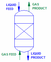
The Gas enters the at Stage 1 of the unit, while the Liquid (or Solid) stream enters at the Final stage of the unit (if there is only a single stage, then both feeds enter Stage 1). The user may specify any number of stages from 1 to 5 in the unit. The Liquids or Solids flow from the Final stage to the Stage 1, while Gas flows in the opposite direction from the Stage 1 to the Final stage. The user may set a Gas bypass at each stage of the unit and the Gas flow may also have a nominal pressure gradient.
This model can be used to emulate a number of unit operations that involve contacting gas with liquids or solids, including Absorbers, Kilns, Scrubbers, etc.

Each stage in the model has an Evaluation Blocks (EB), and hence the user may enable Reactions (RB), Vapour-Liquid Equilibrium (VLE), Solubility (PC) and Environmental Heat Loss (EHX) in each stage. These may be evaluated in any order.
At each stage, the Liquid and Gas streams from previous and succeeding stage are combined and the Evaluation Block is applied to the resulting stream. The contents are then phase split, with the Gas being sent towards the Final stage and the Liquor sent to Stage 1. The evaluations are done in parallel for a number of iterations. At least as many iterations as there are stages are needed to propagate changes in the feeds to the products.
At each stage entrainment of Solids or Liquids into the Gas, as well as Gas into the Liquor, may be specified.

Available Sub-Models
The following sub-models may be enabled in any, or all, of the stages:
- Solubility may be enabled in any stage, if this is NOT enabled globally.
- The Reaction Block (RB) allows the user to configure any number of reactions within a stage.
- The Environmental Heat Exchanger Block allows the user to add or remove energy from a stage using a number of different methods.
- The Vapour Liquid Equilibrium Block may be enabled in any stage.
Diagram
 OR
OR 


- The diagram shows default drawings of the Multi-Stage Counter Flow Tie with connecting streams.
- The physical location of the streams connecting to the Multi-Stage Counter Flow Tie is unimportant. The user may connect the streams to any position on the unit.
- When inserting a Multi-Stage Counter Flow Tie into a flowsheet, the user may choose a different symbol from the menu.
Inputs and Outputs
| Label | Required Optional |
Input Output |
Number of Connections | Description | |
| Min | Max | ||||
| Liquid Feed | Required | In | 1 | 10 | Inlet liquid or slurry stream to the Final Stage of the unit. |
| Gas Feed | Required | In | 1 | 10 | Inlet Gas stream to the Stage 1 of the unit. |
| Liquid Product | Required | Out | 1 | 1 | Product Liquid or Slurry outlet from the Stage 1 of the unit. |
| Gas Product | Required | Out | 1 | 1 | Product Gas outlet from the Final Stage of the unit. |
Behaviour when Model is OFF
If the user disables the unit, by un-ticking the On tick box, then the following actions occur:
- All material in streams connected to the Gas Feed inlets will flow straight out of the Gas Product outlet, with no exchange with material entering through the Liquid Feed;
- All material in streams connected to the Liquid Feed inlets will flow straight out of the Liquid Product outlet, with no exchange with material entering through the Gas Feed;
- No sub-models will be called.
So basically, the unit will be 'bypassed' without the user having to change any connections.
Model Theory
In Steady State, all the Gas Feed streams are perfectly mixed, the Bypass stream is removed and the remaining Gas is added to Stage 1. Similarly, all of the Liquid Feed streams (which may also contain Solids) are perfectly mixed and added to the Final Stage (which may also be Stage 1 if the user has only selected a single stage).
Any sub-models that have been enabled in any of the Stages are carried out on the mixture.
The Liquids and Gases are split after each stage and the Gases are sent to Stage n+1, while the Liquids (and Solids) are sent to Stage n-1. The Liquid and Gas streams may contain some entrainment of the other phase, if defined by the user.
Flow Chart

Data Sections
The default access window consists of several sections:
- CFMultiTie - The first tab contains general information relating to the unit and allows the user to set the number of stages, Gas bypass, Entrainment, etc.
- EB1 - This tab allows the user to enable sub-models in the First stage of the unit. If more than one stage is enabled, then the additional stages will all have a separate page, names EB2, EB3, etc. with the same fields as shown on this page.
- PC1 - Optional tab, only visible if the Solubility is enabled in any of the Evaluation Blocks. Each stage may have a PC tab page.
- RB1 - Optional tab, this tab will be visible for any stages that have Reactions enabled in the Evaluation Block.
- EHX1 - Optional tab, this tab will be visible for any stages that have EnvironHX enabled in the Evaluation Block.
- VLE1 - Optional tab, this tab will be visible for any stages that have Vapour Liquid Equilibrium (VLE) enabled in the Evaluation Block.
- QGx - Optional tab, only visible if a Gas flow is enabled in the field Stream2View. This page shows the properties of the selected Gas stream.
- QLx - Optional tab, only visible if a Liquid flow is enabled in the field Stream2View. This page shows the properties of the selected Liquid/Solid stream.
- Info tab - contains general settings for the unit and allows the user to include documentation about the unit and create Hyperlinks to external documents.
- Links tab, contains a summary table for all the input and output streams.
- Audit tab - contains summary information required for Mass and Energy balance. See Model Examples for enthalpy calculation Examples.
CFMultiTie
Unit Type: CFMultiTie - The first tab page in the access window will have this name.
Tag (Long/Short) |
Input / Calc |
Description
|
| Tag | Display | This name tag may be modified with the change tag option. |
| Condition | Display | OK if no errors/warnings, otherwise lists errors/warnings. |
| ConditionCount | Display | The current number of errors/warnings. If condition is OK, returns 0. |
| GeneralDescription / GenDesc | Display | This is an automatically generated description for the unit. If the user has entered text in the 'EqpDesc' field on the Info tab (see below), this will be displayed here. If this field is blank, then SysCAD will display the UnitType or SubClass. |
| Requirements: | ||
| On | Tickbox | This variable in used to turn the unit ON or OFF. If the unit is OFF, the Gas will flow out of the Gas outlet with no change in state, and the Liquids will flow out of the Liquid outlet with no changes. So, the phases will not contact each other at all. |
| Stages | List | The user may select between 1 and 5 stages in the unit. |
| Iterations | Input | Number of internal iterations for solver convergence. |
| Stream2View | List | The user may select to display none or any of the internal Gas or Liquid streams. |
| Pressure Control
This allows the user to set if the pressure is fixed or varies across the unit. | ||
| StagePressure | Fixed (Gas Feed Reference) | In this case there is no pressure drop across the unit and the Liquid and Gas exit the unit with the same pressure as the pressure in the First Stage (the Gas Feed stage) of the unit. (This pressure is set in the field OperatingP - Method) |
| Fixed (Liquid Feed Reference) | In this case there is no pressure drop across the unit and the Liquid and Gas exit the unit with the same pressure as the pressure in the Final Stage (the Liquid Feed stage) of the unit. (This pressure is set in the field OperatingP - Method) | |
| Linear (Calc dP) | In this case the unit calculates the Total pressure drop across the unit based on the Gas and Liquid Feed pressures. The Total pressure drop is then divided evenly across all of the stages. | |
| Linear (User dP Gas Feed Ref) | In this case, the First Stage (the Gas feed stage) is taken as the reference pressure and the user specifies the pressure drop across each stage of the unit. So, the pressure in the Final stage (the Gas exit stage) will be calculated. | |
| Linear (User dP Liquid Feed Ref) | In this case, the Final Stage (the Liquid feed stage) is taken as the reference pressure and the user specifies the pressure drop across each stage of the unit. So, the pressure in the First stage (the Gas entry stage) will be calculated. | |
| Individual | The user may specify the pressure in each individual stage. | |
| StageDP_Reqd | Input | This field is only visible if StagePressure = Linear (User dP Gas Feed Ref) or Linear (User dP Liquid Feed Ref). The user sets the pressure drop that will be applied across each stage in the unit. |
NOTES on OperatingP section:
| ||
| OperatingP - NOTE: this pressure is applied to the (combined) feed, before sub-models (if any). | ||
| Method | AutoDetect | If there are any liquids AND no vapours present in the feed, outlet streams will take the highest pressure of the feeds. Else (e.g. some vapours present) outlet streams will take the lowest pressure of the feeds. |
| LowestFeed | Outlet streams will take the lowest pressure of the feeds. | |
| HighestFeed | Outlet streams will take the highest pressure of the feeds. | |
| Atmospheric | Outlet streams will be at Atmospheric Pressure. The atmospheric pressure is calculated by SysCAD based on the user defined elevation (default elevation is at sea level = 101.325 kPa). The elevation can be changed on the Environment tab page of the Plant Model. | |
| RequiredP | Outlet streams will be at the user specified pressure. | |
| IgnoreLowMassFlow / IgnoreLowQm | Tick Box | This option is only visible if the AutoDetect, LowestFeed or HighestFeed methods are chosen. When calculating the outlet pressure and temperature of the tank, SysCAD will ignore the low flow feed streams should this option be selected. The low flow limit is set in the field below. |
| LowMassFlowFrac / LowQmFrac | Input | This field is only visible if the IgnoreLowQm option is selected. This is the amount any stream contributes to the total flow. For example, if the total feed to the tank is 10 kg/s, and this field is set to 1%. Then any feed streams with less than 0.1 kg/s will be ignored in the pressure calculations. |
| PressureReqd / P_Reqd | Input | This field is only visible if the RequiredP method is chosen. This is user specified pressure. |
| Result | Calc | The actual pressure used for the sum of the feeds which will also be the outlet pressure (unless further model options change the pressure). |
| StageDP | Display | The calculated pressure drop across each stage in the unit. This field is not visible if StagePressure = Individual. |
| Stage Requirements
The table shown here allows the user to set the Gas bypass and the entrainment values. The user may set a single value that is applied to each stage by ticking the 'All' box and then setting the required value in the first column. Otherwise, do not tick the 'ALL' box and set the values individually for each stage. | ||
| PressureReqd | Input | This is only visible if StagePressure = Individual. This allows the user to set the pressure individually for each stage, or in the entire unit if the 'All' tickbox is enabled. |
| GasBypass | Input | This allows the user to set the Gas bypass, as a single value applied to each stage (All = ticked), or individually for each stage (All = unticked). |
| Entrainment | ||
| VapToLiqStream/VapToLiq | Input | This allows the user to set the Vapour entrainment in the Liquid stream, as a single value applied to each stage, or individually for each stage. |
| SolToGasStream/SolToGas | Input | This allows the user to set the Solid to Gas entrainment, as a single value applied to each stage, or individually for each stage. |
| LiqToGasStream/LiqToGas | Input | This allows the user to set the Liquid to Gas entrainment, as a single value applied to each stage, or individually for each stage. |
| Stage Results Summary
The table shown here gives a summary of the conditions in each of the individual stages. | ||
| Pressure/P | Display | The exit pressure from each individual stage. |
| VapMassFlow/VQm | Display | The Gas flow from each individual stage. |
| LiqMassFlow/LQm | Display | The Liquid flow from each individual stage. |
| SolMassFlow/SQm | Display | The Solids flow from each individual stage. |
| TempIn/Ti | Display | The Temperature into each individual stage (after the Gas and Liquid/Solid steams are combined, but before any sub-models are evaluated.) |
| TempOut/To | Display | The Temperature out of each individual stage. |
| Stream Summary
The table shown here gives a summary of variables in each of the internal Gas (from GasFeed to GasProd) and Liquid/Solid (from LiqFeed to LiqProd) streams between the stages. | ||
| MassFlow/Qm | Display | The mass flow in the individual internal streams. |
| VapourFrac/Vf | Display | The Vapour fraction in the individual internal streams. |
| Temperature/T | Display | The Temperature of the individual internal streams. |
EBs
Each Stage has its own EB section. The user may enable the required sub-models in each stage.
| Tag (Long/Short) | Input / Calc | Description/Calculated Variables / Options |
| Stage X Evaluation Block | ||
| Solubility.On | Tickbox | Only visible if Solubility has been defined for at least one species in the project. Allows the user to switch on any predefined solubility curve to adjust the composition of material in the unit. |
| [email protected] | Tickbox | Only visible if Phase Change at Temperature has been defined for at least one species in the project and Plant Model - Species Tab - PhaseChange@T = OFF. Allows the user to switch on any predefined phase changes at temperature in the unit. |
| EvalSequence | Calc | The sequence in which the sub models (which are part of the evaluation blocks) will be calculated. The sequence is determined by the priority selection for the individual sub-models. Note: If the user chooses On-AutoSequence then SysCAD will determine the sequence of the sub-models. The auto evaluation sequence followed will be the order the sub models are listed below. |
| Reactions | List | Reaction Block (RB) - Enable or disable Reactions and set the sequence in relation to the other sub-models. If this is 'On' then the associated page, RB becomes visible and may be configured. Note: The user does not have to configure a reaction file, even if this block is checked. |
| EnvironHX | List | Environmental Heat Exchanger (EHX) - Enable or disable Environmental Heat Exchange and set the sequence in relation to the other sub-models. If this is 'On' then the associated page, EHX becomes visible and may be configured. Note: The user does not have to configure an environmental heat exchange, even if this block is checked. |
| VLEquilibrium | List | Vapour Liquid Equilibrium (VLE) - Enable or disable Vapour Liquid Equilibrium and set the sequence in relation to the other sub-models. If this is 'On' then the associated page, VLE becomes visible and may be configured. Note: This option may automatically adjust the species make-up. |
Adding this Model to a Project
Add to Configuration File
Sort either by DLL or Group:
| DLL: | Basic2.dll |
→ | Units/Links | → | Process: Tie - Multistage Counter Flow | |
| or | Group: | Energy Transfer |
→ | Units/Links | → | Process: Tie - Multistage Counter Flow |
See Model Selection for more information on adding models to the configuration file.
Insert into Project Flowsheet
| Insert Unit | → | Process | → | Tie - Multistage Counter Flow |
See Insert Unit for general information on inserting units.
Hints and Comments
- There may be mass entering or leaving the unit via the Reaction Block source or sink, so if the outgoing mass is not the same as the incoming mass, this may be a place to check first.
Example Project
- Nickel Copper Project - flowsheet 6.
- Demo Lithium Carbonate CRM Project - flowsheet 1.