Links Table
Navigation: Models ➔ Common Sections ➔ Links
| Model Tab | Optional Input Content Tabs | Optional Material Content Tabs | Optional Material Flow Tabs | Common Tabs | |||||||
|---|---|---|---|---|---|---|---|---|---|---|---|
| UnitType | Content Section | DSp Section | Content | Sp | EC | Qo | Sp | EC | Info | Links | Audit |
This page is for Build 139 or later. For Build 138 or earlier, please refer to Links Table 138.
General Description
This section details the 'Links' page for all units in SysCAD. The Links tables displayed on the Links page give different summaries of the Input and Output streams, displaying streams between units separately to material entering and exiting the project. Units in Dynamic projects will have additional Direct Links for Spill and Vent streams, but otherwise the tables will be similar.
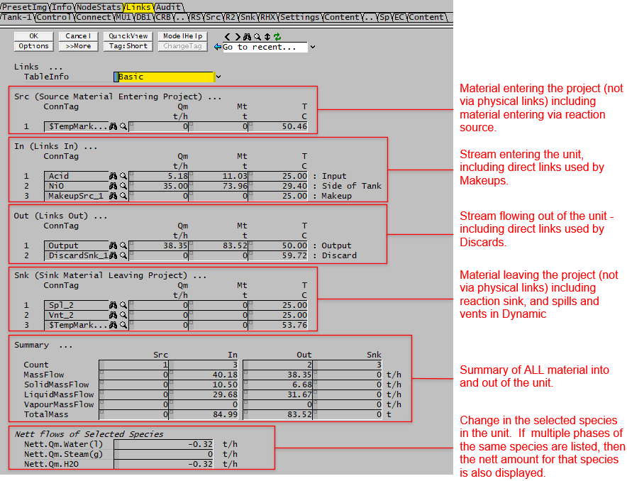
The image below is for a Tank in Dynamic mode, it shows the information displayed in the Basic mode:
TableInfo
| Links ... | ||
| TableInfo | Basic | The links table will be displayed with basic information only, these include Mass flow and Temperature in steady state mode, and additional mass column in dynamic mode. |
| Detailed | The links table will be displayed with additional information, including volumetric flow, pressure, total heat of formation, connection information and link type. | |
Tables: Src, In, Out and Snk
The streams in and out information will be displayed in upto four tables, these are:
- Src (Source Material Entering project) - this is used to display material being added to the project, such as Feeder (not cross page connections) or reaction source
- In (Links In) - these are inputs with connection links, either user connected (from upstream) or direct links such as makeup stream.
- Out (Links Out) - these are outputs with connection links, either user connected (to downstream) or direct links such as discard stream.
- Snk (Sink Material Leaving Project) - this is used to display material being removed from the project, such as a product sink (not cross page connections) or reaction sink.
The column headings for these 4 tables are described below:
| Column Heading | Description |
| The following fields are visible when TableInfo = Basic | |
| first column | The link index number. Links are numbered from 1. |
| ConnTag | Link Name or Source/Destination Name for Direct Links (Makeups, Discards, Spills, etc.). For reaction source and sink (with no connected links), a temporary tag will be assigned to them so they can be listed in the table. |
| Qm | Mass flow through the link. The user may choose to display this in any conversion units. |
| Mt | Only visible in Dynamic projects. Total Mass that has flowed through the link in the current SysCAD run. The user may choose to display this in any conversion units. |
| T | The temperature of the material flowing through the link. |
| description on RHS | For Unit models, the PortID of this unit models connections are shown. For Pipes the UnitType and connected unit model PortID is shown. |
| The following additional fields are visible when TableInfo = Detailed | |
| Qv | Volumetric flow through the link. The user may choose to display this in any conversion units. |
| P | The pressure of the material flowing through the link. |
| totHf | Total Heat of formation at stream conditions. The user may choose to display this in any conversion units. |
| PortID / ConnIOPort | ("ConnIOPort " prior to Build 139.33098.) The connection PortID for this Unit model for the connection, such as Input, Output, Feed, Overflow, MakeUp1, Vent and so on. For a Pipe this will be either Input or Output. |
| ConnUnitType | The connection unit type, e.g.: Pipe-1, MakeupSource |
| ConnPortID | Available from Build 139.33098. The connection PortID for the connected Unit model (i.e. on the other side of the Flange/DirectLink at the ConnUnitType). |
| LinkType | The internal SysCAD Link type, usually a Pipe or one of the DirectLink types (e.g. Makeup or Discard). |
| LinkTag | The internal SysCAD Link tag, usually of type Flange or DirectLink. |
Summary Table
| Tag | Description |
| Summary... | |
| The first summary lists the overall total. | |
| Count | The total number of connected links (in + out) |
| TotalIn.MassFlow / TotalIn.Qm | The total mass flow for all the connected inputs (from upstream unit), and material sources. Can be used for mass balance around the individual unit operation - total mass flow into the unit. |
| Totalout.MassFlow / TotalOut.Qm | The total mass flow for all the connected outputs (to downstream units), and material sinks. Can be used for mass balance around the individual unit operation - total mass flow out of the unit. |
| The second summary is displayed in a table format, listing the total for the four links tables described above. | |
| Column headings | |
| Src | These are source of material being added to the project, including Feeders (not cross page connections) and reaction sources. Can be used for overall mass balance, see note below. |
| In | Total for all the connected inputs (from upstream unit), includes pipes and makeups |
| Out | Total for all the connected outputs (to downstream units), includes pipes and discards |
| Snk | These are for material leaving the project, including Sink (not cross page connections), reaction sinks, and dynamic project spills and vents. Can be used for overall mass balance, see note below. |
| Row headings | |
| Count | The total number of in and out links connects to the unit |
| MassFlow / Qm | The total flow rate from all links entering and leaving the unit |
| SolidMassFlow / SQm | The Solids only flow rate from all links entering and leaving the unit |
| LiquidMassFlow / LQm | The Liquids only flow rate from all links entering and leaving the unit |
| VapourMassFlow / VQm | The Vapours only flow rate from all links entering and leaving the unit |
| TotalMass / Mt | Only visible in Dynamic projects. Includes: in: The total Mass that has entered the unit from all links in the current SysCAD run out: The total Mass that has exited from the unit from all links in the current SysCAD run. |
NOTE:
- When completing the overall mass balance for the project,
- the total mass flow into the project = sum of all the "Src Mass flow" for individual unit operations.
- the total mass flow out the project = sum of all the "Snk Mass flow" for individual unit operations.
Species Table
This table displays the mass change for selected species across the unit. In Feeders and Sinks this will be due to adding or removing material, in other units it will be due to reactions.
This allows users to produce a mass balance for selected species across either the entire project, or selected areas.
The default species that will be displayed are H2O(l) and H2O(g). However, the user may add additional species, and remove water and steam if required - go to View - Plant Model and see the List of Species to Report nett flows (shown of the Links page):. See NettQm.List on Plant Model Access Window.
Notes:
- This is NOT the amount of the species flowing into and out of the unit in Links.
- This is the amount of the species that actually enters or leaves the project, or is created or consumed in Reactions.
| Tag | Description |
| Configuration | NettQm.List on Plant Model Access Window |
| Nett.Qm.Water(l) / H2O(l) | Displays the mass change of water. This would be 0 if water is not consumed or created. Used to keep track of compound change in reactions & phase change. |
| Nett.Qm.Steam(g) / H2O(g) | Displays the mass change of steam. This would be 0 if steam is not consumed or created. Used to keep track of compound change in reactions & phase change. |
| Nett.Qm.H2O | This variable is automatically added. When a species is added to the list in multiple phases, an extra field is added to show the nett change of the species. For example, Nett.Qm.H2O = Nett.Qm.H2O(l) + Nett.Qm.H2O(g). This is very useful when creating water/steam balances for the project. |
| Nett.Qm.xxx(phase) | Other compounds maybe visible if the user has added species on the Plant Model - Settings Tab, heading Link Balance Species. |
| Nett.Qm.xxx | If multiple phases of the same species are added to the Link Balance Species List, then the species (with no phase specified) will be added automatically to the links table to show nett change for the species. See example for H2O above. This nett flow is useful for component balances. |