FAQ - Flash Train related questions
Navigation: User Guide ➔ Frequently Asked Questions ➔ Flashing / Flash Train Questions
| Frequently Asked Questions (FAQ) and Troubleshooting | |||||||||||||
|---|---|---|---|---|---|---|---|---|---|---|---|---|---|
| General Questions | Installation Related | License Related | Project Related | Species Related | Modelling Related | TCE Related | Graphics Related | Access/Trend Related | Reactions Related | Mass & Energy Balance | Flashing / Flash Train | PGM Related | Dynamic Related |
Latest SysCAD Version: 19 March 2024 - SysCAD 9.3 Build 139.35102
Related Links: Getting Started
Troubleshooting Flash Trains
To troubleshoot Flash Train convergence issues, please refer to Troubleshooting Flash Trains.
Why is the display colour of some models dark-blue?
SysCAD uses Colours to display the unit operation's status.
Generally, while using the default white SysCAD background Scheme colour, when the display colour of a model is dark blue, they are part of a macro model, or a Flash Train model.
With a black SysCAD background Scheme colour (default for earlier versions of SysCAD), the flash train will be displayed in white.
What are macro models?
Macro model is the name given to a Flash Train. When models such as Flash Tanks and heat exchangers are correctly connected together, a flash train will be formed.
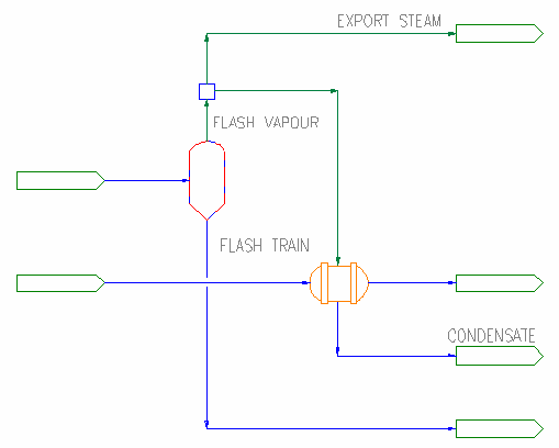
For example, a flash tank and a shell and tube heat exchanger have formed a Flash Train. These two unit operations will be displayed in dark blue (with white background scheme colour). When models are under the flash train mode, SysCAD calculates the amount of steam being flashed off the flash tank based on the shell and tube exchanger configuration.
For more information see Flash Train.
Using a Tie without breaking a Flash Train
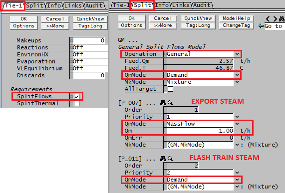
If a tie is added in the vapour line connecting the flash tank to the heat exchanger steam inlet, the flash train will not be formed automatically unless the user does the following:
- Open the tie Access Window, and enable 'SplitFlows' under the Options heading;
- Click on the 'Split' tab and select the 'General' option from the Operation drop down list;
- The QmMode for the stream feeding the heat exchanger must be in 'Demand';
- You may change the QmMode for streams that are exiting the Flash Train to any other option.
Using a Tie to 'Break' a Flash Train
Adding a tie in the middle of a flash train can break the flash train. For example, if you have connected the flash tank vapours to a Barometric condenser, SysCAD will automatically put them in a flash train configuration. If you want to break the flash train so that you can control the flash tank pressure manually, add a tie in the vapour line to the Barometric condenser, do not turn on the GM model in the tie and the flash train configuration will be broken.
Energy Balance Error in Flash Train
|
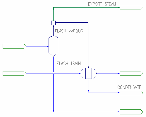
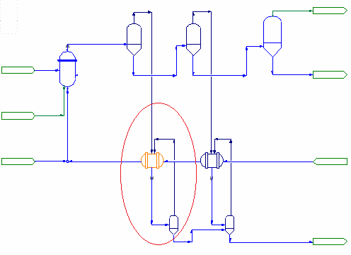
For example, if you have a flash train configuration as shown here and when you solve the flowsheet, you get an energy balance error in the heat exchanger (marked orange). First, we need to understand what SysCAD does in a Flash Train configuration.
What we can do to help SysCAD is to avoid this unnecessary complication by either Turning the Reflash 1 Offline or remove Reflash 1 altogether. In both cases, the Shell & Tube HX 1 condensate will feed directly into Reflash 2 where a solution can be obtained. |
Exporting Steam in a Flash Train
I need to flash / condense a species other than water, what should I do?
To enable flashing/condensing of a species, user must specify the vapour pressure data for the species. The vapour pressure data for H2O is included in SysCAD. Users can add new species to the list by following these steps:
We will use ammonia as an example:
- Edit the SysCAD Database to include both the liquid and vapour phase of ammonia.
- For NH3(g), make sure the field Vp and Tc contain valid data. (See Species Table - Vapour Pressure for further information.)
- Next, close any opened projects and edit the project configuration file to include NH3(g) and NH3(aq) in the Display List. (See Species Configuration for further information.)
- Caution SysCAD VLE currently only supports a single liquid phase species. Only one of NH3(aq) and NH3(l) can be used within VLE calculations (the other is ignored).
- Reload the project and the ammonia should be available as a flash component.
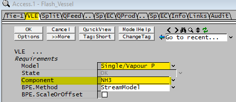
- Choose ammonia from the VLE Tab Component droplist.
If you have two or more flashing species, then you can:
- Set Water as the flashing component, then with the remaining components, use a reaction file to set the flashing extent for each (e.g.: HCl).
- To control the reaction extent of flashing component, e.g.: HCl, you can use a PGM side calculation to workout the partial pressure of HCl, then adjust the extent using the PGM or PID controller.
- The sub model evaluation order should be Reactions, then VLE.
The LMTD displayed is wrong
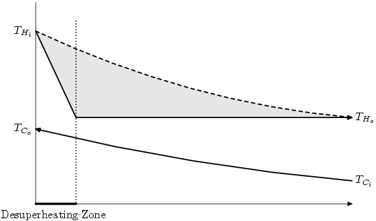
It is not wrong. It is calculated from the condensing temperature of the vapour, rather than the actual terminal temperatures. Here is what is going on - this shows the temperature profiles along the length of the heat exchanger (condenser) for the cold and hot sides:
In summary, the LMTD displayed in the heat exchanger model is calculated from the liquor terminal temperatures and the vapour condensing temperature and that is a perfectly adequate assumption for basic design. In the real world, you are lucky if you know your heat transfer coefficients to within 20%.
Why is the steam vapour pressure not equal to atmospheric pressure at 100°C?
If you have a saturated steam stream at 100°C you find the pressure is actually 101.418kPa, or 1.0009 atm, which differs from 1atm by one tenth of one percent. Or if you set the pressure to 0barg (1atm), the temperature is not exactly 100°C.
The Celsius scale has been refined over the years from its original incantation, where the freezing point of water was set at 0°C, and the boiling point of water at atmospheric pressure to 100°C. The latest temperature scale defines temperatures at a number of points such as the melting point of gallium and the triple point of hydrogen. The only water value it uses is the triple point of water of 273.16 K. On this new scale, water actually boils at 99.974°C. SysCAD implements the IF97 steam model, which uses this revised temperature scale.
In practical terms this difference is minute: it would be the difference in boiling point due to an elevation change of about 8 m.
What is the difference between BPE@T and BPE@P
There are two different ways to display Boiling Point Elevation (BPE) - as a function of pressure and as a function of temperature. For saturated liquids the two give identical results, they differ when you have a nonsaturated (subcooled) liquid and only if the boiling point elevation has a temperature dependency as well. The Alumina3 properties model displays both BPE@T and BPE@P.
For a subcooled liquid, we can get to saturation (boiling/flashing) by either
- Raising the temperature at a fixed pressure
- Lowering the pressure at a fixed temperature.
The two different BPE displays relate to these two scenarios -- once we reach saturation, either the liquor temperature has changed or the pressure has changed, and because of the temperature dependence of BPE, the liquors are in different thermophysical states and we should expect the properties (including BPE) to be different as well.
For example, suppose you are specifying operating conditions for a charge pump in a digestion system where live steam is used to heat an incoming liquor in a heat exchanger. To avoid boiling in the tubes (with resulting loss of efficiency and possible pitting and damage to heat transfer surfaces), the charge pump is operated at some margin over the liquor vapour pressure. In this case it is the BPE@P which is relevant to the calculation - if BPE@P is ten degrees and we are operating the charge pump at 6MPa, then the liquor boiling point of 285°C is immediately determined from the water boiling point of 275°C, and we can control live steam flow to provide a suitable margin.
How do I add just enough steam without having to vent off excess steam without using a flash train?
For example, if you have a stand-alone direct contact heater with steam feed coming from a tie. The heater is not part of a flash train and therefore it does not know the correct amount of steam to add given the required temperature. What can be done to get just enough steam addition without having to vent off excess steam?
First, we need to understand what happens in the direct contact heater. When steam is added, enough of it is condensed to achieve the required temperature or temperature rise. A built-in controller is used to do this work. Now, a problem arises when there is too much steam added, as SysCAD does not know how to reduce this normally, so the excess steam is vented. This is done either through the Excess steam vent or if one is not connected, then it either goes out with the hotliquor or is vented (disappears) if the VentExcessSteam tick box is selected.
The problem arises when the user want to add just enough steam to the contact heater without having to loose this excess steam. When a contact heater is in demand mode, an extra built in PID controller is used to control the amount of steam added so that there is no excess steam.
A direct contact heater is in the demand mode when 1) it is part of a flash train, 2) when its steam supply comes directly from a feeder with the demand mode ticked (see models help for more explanations). If the steam comes from a tie that's not part of a flash train, it is not in demand mode.
Under this situation, the only way to fix the excess steam problem is to add a user defined PID controller to control the amount of steam added so that a required hotliquor temperature is met. Now, as mentioned before, the direct contact heater has already a built in controller to control its hotliquor temperature, therefore, once the user defined controller is added, there will be a conflict between the two controllers.
To avoid this, we have to make the user-defined controller take control. To do this, we will purposely set a temperature in the contact heater that will be unachievable, thus slightly higher than the actual required T. For example, if the set point for the user defined PID controller is 125 C. Then we will put in 125.01 for the Required Temperature in Contact heater.
The idea behind this is to never let the contact heater internal controller arrive at its setpoint. If your internal contact heater never gets "enough" steam, then there will be NO excess steam.
