Example 65 Smelting
Jump to navigation
Jump to search
Navigation: User Guide ➔ Example Projects ➔ 65 Smelting
Copper Flash Furnace Example
Project Location
..\SysCADXXX\Examples\65 Smelting\Copper Flash Furnace Example.spf
Features Demonstrated
- Simulation of a complex unit operation(Flash Furnace) as three simpler unit operations (Shaft section, Settler Section and Uptake)
- The use of Evaporative Dryer
- The use of Makeup Sources and Makeup Blocks
- The use of Reaction Blocks
- The use of PID controllers
Brief Project Description
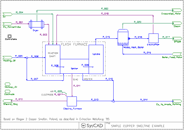
- This is a very simplified model of a smelter section. The project was created based on Glogow 2 Copper Smelter, Poland, as described in Extraction Metallurgy 1985.
- Copper concentrate is dried and fed into the furnace, where Cu is smelted and sent to Anode Refining. Heating Oil is used to provide energy to the smelter.
- The main focus of this project is the simulation of the flash furnace. The Flash Furnace, being a complex unit operation, is very difficult to simulate as one unit operation. To overcome this, the flash furnace was broken down to three smaller sections, these are modelled as Reaction Shaft, Settler Section and uptake offgas.
- Both the reaction shaft and Settler sections contain reactions.
- The Settler section has multiple outlets, where the slag and metal and offgas are drawn out.
- The slag is sent to an electric furnace to extract out more metal.
- Energy is recovered from the offgas in the waste heat boiler.
- Fines in the offgas is filtered out and returned to the Furnace.
Project Configuration
- One of the important aspects of this project is the definition of species/compounds in the species database.
- Compounds are defined in Solid, Slag, Molten, liquid and vapour phases
- Reactions are used to convert compounds into the correct phases
- Separation of Flow is based on individual phases
Included Excel Report
StandaloneReport.xls, this file has the following reports:
- Summary
- Criteria
- Flowsheet with stream values
- Feed composition
- Reactions
- Stream values
- Mass Balance
- Energy Balance
- Energy Balance Diagram
FerroManganese Furnace Example
Project Location
..\SysCADXXX\Examples\65 Smelting\FerroManganese Furnace Example.spf
Features Demonstrated
- Simulation of a complex unit operation (Furnace) as four simpler unit operations (Drying, Indirect Reduction 1, Indirect Reduction 2 and Direct Reduction Zones), with streams connected both to and from adjacent units.
- The use of Makeup Sources and Makeup Blocks
- The use of Reaction Blocks
- The use of PID controllers
- The use of General Controllers to provide control options
- The use of Model Procedures
Brief Project Description
Simulation of FerroManganese Furnace as four zones to produce metal, slag and offgas streams.
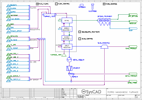
- This is a simplified model of a smelter which is represented by four ties corresponding to four zones: Drying, Indirection Reduction 1, Indirection Reduction 2 and Direct Reduction. Solids and liquids are transferred to the next zone. Gases (with any particulate matter) are transferred back to the previous zone. All four zones contain reactions.
- Energy is added to the smelter in the Direct Reduction zone via RHX. The amount of energy added will always be enough to achieve the target smelter temperature. An error message will be received if the required power exceeds the user specified maximum power.
- Heat loss in each zone can be specified using the EHX sub-model.
- Boudouard reactions (C + CO2 -> CO) in each zone can be controlled based on equilibrium CO/CO2 compositions at the zone temperature.
- Air can be added to the first two zones if the option for an open smelter is enabled. Required oxygen gas is added via Reaction Sources in the Drying and Indirect Reduction 1 zones. Nitrogen gas is added to the first two zones via Makeup Blocks in proportion to the oxygen.
- Carbon Electrode is added to the Direct Reduction zone via a Makeup Block, based on a user specified electrode usage rate (kg/MWh).
- A mixture of ores, reductants and fluxes is fed into the furnace, where Mn and other metals are smelted and sent to the metal cooler.
- Gases (with any particulate matter) exit the smelter via the Drying zone and are separated into dry offgas, moisture and dust in the Offgas Treatment unit. The offgas can be cooled and steam condensed.
- Slag from the Direct Reduction zone is sent to the Slag Stockpile. The slag can be cooled and solidified via a Reaction Block and some can be recycled to the furnace feed.
- Excess carbon and potassium can sent from the Direct Reduction zone to the furnace sink.
- Metal product can be cooled and solidified via a Reaction Block in the metal cooler. The crusher and screen are represented by tie models. The screen oversize is the metal product. A proportion of the screen undersize (fines) can recycled to the furnace feed.
- A variety of feeds can be used including up to 5 fluxes, 3 reductants and 6 manganese ores. Some of these are controlled via PID controllers as described below.
- Manganese fraction in metal product can be controlled by varying iron ore or manganese ore feed flows.
- Maximum carbon in metal product is calculated and controlled by varying reductant feed flows.
- A variety of Basicity calculations are performed in a Model Procedure. The feed flux flow can be varied to achieve a target basicity.
- The slag to alloy ratio can be controlled by varying the slag recycle or the total flux feed flow.
- The MnO in the slag can be controlled by varying appropriate reaction extents, with the target being calculated by a relationship with basicity and temperature.
- The total feed can be controlled to achieve either a target ore feed, total feed, metal product, slag product or total metal and slag product.
Project Configuration
- Most units are simulated by the Tie model.
- One of the important aspects of this project is the definition of species/compounds in the species database.
- Compounds are defined in Solid (s), Particulate (p), Slag (sl), Molten (ml), liquid (l) and vapour phases (g).
- Reactions are used to convert compounds into the correct phases.
- Separation of flow is usually based on individual phases using the GM sub-model.
Included Excel Report
FeMn Furnace Report.xlsx
This file has the following reports:
- Criteria
- Composition and flows of feeds
- Reactions
- Flowsheet with stream values

