Example 30 Lithium
Jump to navigation
Jump to search
Navigation: User Guide ➔ Example Projects ➔ 30 Lithium
Demo Lithium Carbonate CRM Project
Project Location
..\SysCADXXX\Examples\30 Lithium\Demo Lithium Carbonate CRM Project.spf
Features Demonstrated
- The use of Multi-Stage Counter Flow Tie to simulate a kiln with reactions
- The use of Simple Heat Exchanger and Shell and Tube Heat Exchanger
- The use of Simple Condenser
- The use of Filter Press model
- The use of Makeup Sources and Makeup Blocks
- The use of Discard Sink and Discard Block (DB)
- The use of Reaction Blocks, including the use of Heat Exchange and Final Concentration extent type
- The use of Composition Fetch
- The use of PID controllers
- The use of Set Tag Controllers
- The use of a General Controller to check for incorrect results and produce condition error
- The use of EHX and VLE sub-models
- The use of Split Flows Gas Vent option
Brief Project Description
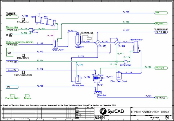
- This is a simplified model of a Lithium Carbonate plant. The project is based on the proposed Rose Tantalum-Lithium Project in Canada, as described in "Technical Report and Preliminary Economic Assessment on the Rose Tantalum-Lithium Project", by Genivar Inc, December 2011 (http://www.cecorp.ca/documents/en/pea_final_techreport.pdf). This document refers to the process developed by "Centre de Recherche Minerale (CRM)".
- Spodumene concentrate is fed into the kiln, where alpha-spodumene is converted to beta-spodumene and all water is evaporated
- Heating of the kiln to 1038 °C is achieved by feeding hot gases from the burner to the kiln, counter-current to the solid feed. The hot gas bypasses the final stage of the kiln, where the solid product is cooled to 800 °C.
- Cooled solid product is mixed with recycled sodium carbonate solution in the Pulper Tank.
- The slurry from the Pulper Tank is fed to the high pressure Autoclave where the beta-spodumene is converted to solid lithium carbonate using the CRM (Centre de Recherche Minerale) process.
- The autoclave product is cooled by the Filtrate and then by the evaporation of liquid CO2.
- In the high pressure Bicarbonator lithium and sodium carbonates are converted to soluble lithium and sodium bicarbonates by reacting with CO2 gas
- Excess CO2 is vented from the Filter Feed Tank and Filter Press, with most being recycled back to the Bicarbonator.
- The filter press cake is washed with Wash Water based on a defined wash ratio. The washed filter cake is repulped with process water before being sent to the Tail Pond.
- The filtrate exchanges heat with the Autoclave product and then is sent to the Precipitator.
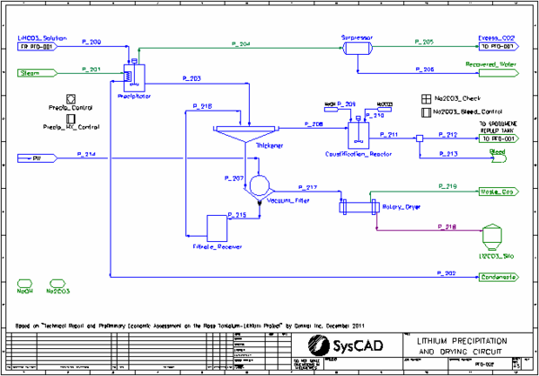
- In the Precipitator lithium bicarbonate precipitates as lithium carbonate, liberating CO2 gas.
- The vent gas from the Precipitator is sent to a surpressor where all the steam is condensed and removed. The CO2 gas is recycled back to the Bicarbonator.
- The slurry from the Precipitator is sent to a Thickener.
- The Thickener overflow is sent to a Caustification Reactor where sodium hydroxide is added to convert the remaining sodium bicarbonate to sodium carbonate. Additional sodium carbonate is added to achieve a saturated solution. The desired amount is recycled back to the Pulper Tank, with excess being bleed from the process.
- The Thickener underflow is sent to the Vacuum Filter. The filter cake is washed with Wash Water based on a defined wash ratio. The filtrate is recycled back to the Thickener.
- The washed filter cake is sent to the Rotary Dryer where all water evaporates, to produce the lithium carbonate product.
Project Configuration
- Most units with reactions are simulated by the Tank or Tie model. This includes the Pulper Tank, Autoclave, Bicarbonator, Precipitator, Surpressor, Causticfication Reactor and Rotary Dryer. The suppressor is modelled as simple condenser.
- Separation of gases and slurry is usually achieved by the use of Split Flows Gas Vent option
- The kiln is modelled by a Multi-Stage Counter Flow Tie with four sections/stages. Reactions are enabled in sections 2 and 4, EHX is enabled in section 1. Gas bypasses the first section.
- Makeup Blocks are used:
- in the Burner to add oxygen gas using a MassRatio
- in the Caustification Reactor to add a stoichiometric amount of sodium hydroxide
- in the Caustification Reactor to add sodium carbonate to achieve a specified (saturated) concentration
- Composition Fetch is used in the Sodium Carbonate Solution feeder to allow the connection to the second flowsheet to be broken.
- VLE is enabled in the Pulper Tank and Precipitator to allow the correct evaporation of water.
- HX_001 is modelled by a Simple Heat Exchanger with the ProductT option.
- HX_002 is modelled by a Shell and Tube Heat Exchanger in Fully Evaporating mode.
- The Filter Press and Vacuum Filter are modelled by the Filter Press model using the SolidsFractionInFiltrate and Constant Wash Efficiency methods.
- The Thickener uses the OverflowSolidsFraction method and has EHX enabled to allow a temperature drop
- PID controllers are used to:
- control the kiln temperature by adjustment of the natural gas flow
- control the Bicarbonator feed temperature by adjustment of the CO2 liquid flow
- control the Precipitator temperature by adjustment of the steam flow
- Set Tag Controllers are used to:
- set wash water flows based on user specified ratios to both filters
- transfer the heat from the Precip HX to the Reaction Heat Exchange of the Precipitator
- control the split of sodium carbonate solution to achieve desired flow to Autoclave. This is done by setting both the split after the Caustification Reactor and setting the Sodium Carbonate Solution feeder, thus allowing the cross-page connection to be broken. This assists in model stability when there are large changes in feed flow.
- The Na2CO3_Check General Controller checks that the Na2CO3 solution flows on both flowsheets match. If they do not then it produces a condition error to alert the user.
Included Excel Report
Lithium CRM Example Report.xlsx
This file has the following reports:
- Criteria
- Streams
- Mass Balance
Demo Lithium Carbonate Acid Leach Project
Project Location
..\SysCADXXX\Examples\30 Lithium\Demo Lithium Carbonate Acid Leach Project.spf
Features Demonstrated
- The use of Thickener model
- The use of Filter Press model
- The use of Makeup Sources and Makeup Blocks
- The use of Reaction Blocks, including the use of Heat Exchange, Override Product Temperature Option and Final Concentration extent type
- The use of Set Tag Controllers
- The use of a General Controller
- The use of EHX
- The use of Split Flows Gas Vent option
Brief Project Description
- This is a simplified model of a Lithium Carbonate plant. The project is based on the Quebec Lithium Project in Canada, as described in "Technical Report NI 43-101 on the Pre-Feasibility Study for the Quebec Lithium Project", by Canada Lithium Corporation and BBA Inc, May 2010, which was downloaded from the Sedar website (http://www.sedar.com/DisplayCompanyDocuments.do?lang=EN&issuerNo=00007891).
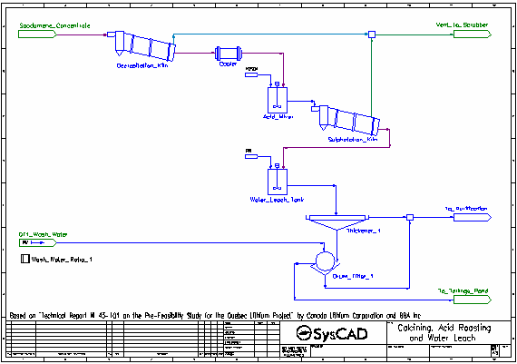
- Dried spodumene concentrate is fed into the Decrepitation Kiln, where alpha-spodumene is converted to beta-spodumene and any water present is evaporated. These reactions occur at 1050 °C.
- The solid product is cooled to 60 °C in the Cooler.
- Cooled solid product is mixed with concentrated sulfuric acid in the Acid Mixer.
- The slurry from the Acid Mixer is fed to the Sulphatation Kiln where the beta-spodumene is converted to solid lithium sulfate by reacting with the sulfuric acid. Oxide impurities are also converted to their sulfate forms by reaction with sulfuric acid. These reactions occur at 250 °C.
- Some excess water is converted to gas. All gases are vented.
- The kiln solids, along with leftover acid, pass to the Water Leach Tank where water is added. The majority of the solid sulfates dissolve in the water.
- The slurry is thickened and send to a drum filter where it is washed with process water. The washed filter cake is sent to the Tailings Pond.
- The filtrate and thickener overflow are combined and sent to the purification processes.
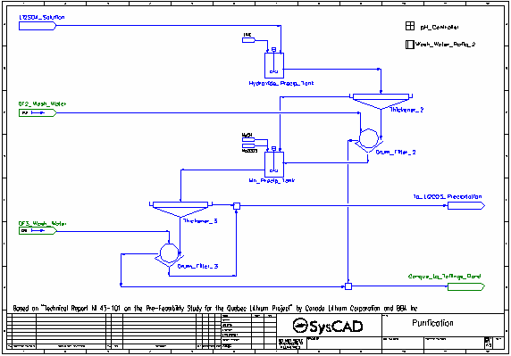
- The pH of the lithium sulfate solution is raised from <2 to around 6 by the addition of Lime, which both neutralises most of the acid present as well as causing the precipitation of aluminium and iron as hydroxides, along with some lithium and manganese, also as hydroxides.
- The resulting slurry is thickened and send to a drum filter where it is washed with process water. The washed filter cake is sent to the Tailings Pond.
- The filtrate and thickener overflow are combined and sent to the second stage of purification.
- The pH of the solution is raised to 10 by the addition of Caustic Soda (NaOH), which both neutralises all remaining acid present as well as causing the precipitation of manganese as hydroxide, along with some lithium, also as hydroxide. Soda Ash is also added to aid in the precipitation of calcium as carbonate.
- The resulting slurry is thickened and send to a drum filter where it is washed with process water. The washed filter cake is sent to the Tailings Pond.
- The filtrate and thickener overflow are combined and sent to the lithium carbonate precipitation tank which is maintained at 95 °C.
- Soda Ash is added to convert the lithium sulfate to lithium carbonate (which precipitates), as well as precipitate a small amount of leftover calcium as carbonate.
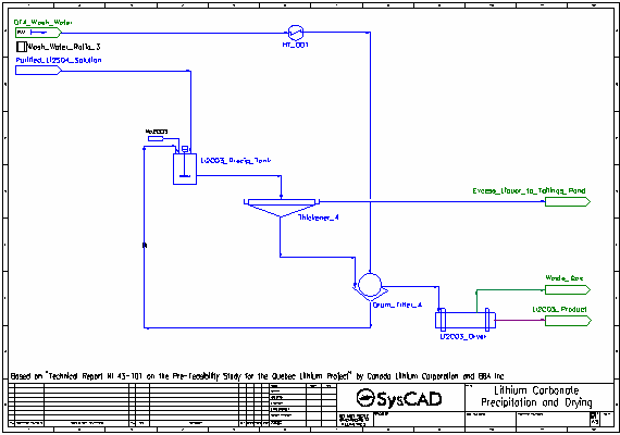
- The resulting slurry is thickened and send to a drum filter. The thickener overflow is sent to the Tailings Pond.
- The thickened slurry is washed with process water (also at 95 °C) in the drum filter. The washed filter cake is sent to the dryer, while the filtrate is recycled back to the lithium carbonate precipitation tank.
- In the dryer, all water is evaporated and aqueous species are returned to the their solid forms. The steam is vented leaving the solid lithium carbonate product.
Project Configuration
- Most units with reactions are simulated by the Tank model. This includes the Decrepitation Kiln, Sulphatation Kiln, Water Leach Tank, Hydroxide Precip Tank, Mn Precip Tank, Li2CO3 Precip Tank and Li2CO3 Dryer.
- Separation of gases and slurry is usually achieved by the use of Split Flows Gas Vent option.
- Makeup Blocks are used:
- in the Acid Mixer to add a slight excess sulfuric acid
- in the Water Leach Tank to add process water to achieve a specified solids fraction
- in the Hydroxide Precip Tank to add a specified molar flow of pure lime
- in the Mn Precip Tank to add a specified molar flow of pure NaOH
- in the Mn Precip Tank to add a stoichiometric amount of Na2CO3
- in the Li2CO3 Precip Tank to add a stoichiometric amount of Na2CO3
- The Cooler is modelled by a Tank with the EHX sub-model enabled to achieve the desired product temperature
- All Thickeners are modelled by the Thickener model using the OverFlowSolidsFraction method.
- All Drum Filters are modelled by the Filter Press model using the SolidsFractionInFiltrate and Constant Wash Efficiency methods.
- Set Tag Controllers are used to set wash water flows based on user specified ratios to all drum filters
- A General Controller is used to control the Lime and Caustic Soda additions in order to achieve the desired pH, via feed forward calculations.
Included Excel Report
Lithium Acid Leach Example Report.xlsx
This file has the following reports:
- Criteria
- Streams
- Mass Balance
