Dynamic Transfer
Navigation: User Guide ➔ Solver ➔ Simulation Modes ➔ Dynamic Transfer
Related Links: Setting Up Transfer Pull Network
Introduction
Transfer Push and Pull for Batch Processes |
Dynamic Transfer is the basic dynamic license option for flow based dynamic simulation. All pipes are modelled as transfer links, where fixed flow capacities are specified directly. The mode easily handles Accelerated time with large step sizes, allowing users to analyse long term forecasts and focus on macro effects and major equipment.
In this mode the user may set the piping networks to either Transfer Push mode of Transfer Pull mode. These two modes are discussed below:
Transfer Push Mode
Transfer Push mode is essentially a ‘Push’ method of calculating flow through a stream, i.e. the first pipe or unit in the "local network" determines the flow through that network.
General Philosophy
- Transfer mode is "effectively" ProBal mode. However Tear streams have "surge" to maintain mass balance.
- Material through the local network is flow based - pressure does NOT influence flows.
- Flow can only be in the forward direction.
- Flow is set either in the Feeder or the exit pipe leaving surge units.
- The pressure change is for display purpose only, it will not affect flow.
Network Identification
- Transfer Push simulation mode is the default Dynamic Transfer simulation mode.
- This mode is required for the correct operation of Mass transfer models such Conveyors, Screens, Mills and Crushers. These units (and more) will automatically force connected pipes that requires the Transfer Push be placed in a Transfer Push Local Network.
- Tank Overflows (with no flow restriction or control) should be placed in Transfer Push mode.
Specifying Flow in Transfer Push Mode
- The feed specification for Transfer Push mode is similar to Steady State, where user specifies the feed requirements in feeders.
- For flow out of Surge units (such as Tanks), user will configure the Tank outlet pipe height and filters (e.g. user may choose to block solids for an overflow connection) inside the tank, as for the actual flowrate capacity, it will be specified in the output PIPE.
- Unit operations such as Pumps, Valves and Piping Systems will act as ON/OFF control, it will either pass / block flow. The flow it will pass through is dependent on the flow specification in the upstream tank exit pipe or upstream connecting feeder (if no surge unit is found in the local network path).
- For single pump valve, recommend the use of Pump2 and Valve2
- For more complex systems without parallel path, we recommend the use of Piping System Model. User can use the piping system model to define a linear collection of pipe segments, pumps and valves.
- For flow network involving parallel path, we recommend using the Transfer Pull Local Network.
NOTE: To use the Transfer Push mode and Pump2 and Valve2 within a complex piping network the user must calculate and set the required feed into the system based on the required flow through each branch of the network. This can lead to long and complex control logic within a General Controller. Transfer Pull may be more suitable to these more complex "local networks".
Rules applied to model configurations are:
- Tank
- Configure the Tank outlet pipe height
- Set outlet stream filters if required
- Flow out is specified in the output PIPE, see below.
See Tank Connect Tab for more information.
- Pipes
- Surge Tank Outlet Capacity is defined in the Pipe model.
- User may set 'Batch Method' in first pipe downstream of a surge unit.
- User may set 'Overcapacity' to 'Spill' or 'Accept' and this will determine the behaviour of pipes where flow > capacity.
- User may optionally set a pressure drop method, and the pressure drop in the pipe will be calculated for display purposes ONLY (i.e. pressure doesn't affect flow).
See Pipe Flow Capacity for more information.
- Pumps
- The Pump in Transfer Push mode will have two options, Run Pump (>0% Speed) or Stop Pump (0% Speed). The flow through the pump when it is on can be specified in any pipe upstream of the pump, usually in the upstream Tank outlet or upstream Connected Feeder.
- User may set a pressure boost method, and this will be used to calculate the pressure from the pump. This is for display purposes ONLY.
The Pump2 piping model has been developed specifically for Transfer Push mode. We recommend using this model for Transfer Push mode.
- Valves
- The Valve in Transfer Push mode will have two options, Open Valve (>0% Opened) or Close Valve (0% Opened). The flow through the valve when it is opened can be specified in any pipe upstream of the valve, usually in the upstream Tank outlet or upstream Connected Feeder.
- User may set a pressure boost method, and this will be used to calculate the pressure from the pump. This is for display purposes ONLY.
The Valve2 piping model has been developed specifically for Transfer Push mode. We recommend using this model for Transfer Push mode.
Ties
- Ties may have GM configured and this will be used to determine the mass split from a tie.
- Users may set the operating pressure in a tie
Transfer Pull Mode
General Philosophy
- The Transfer Pull mode can be viewed as Transfer Push Mode with an additional preliminary step, where SysCAD analyses the local network demands to determine a maximum flow, this flow is then used in the "Push" Transfer mode solution.
- When user specifies a piece of equipment to be included in the network, SysCAD will analyse all surrounding equipment and piping network to identify the local network.
- Once a local network has be established, a demand flow (maximum flow) is calculated and set at the Local Network starting unit.
- A transfer pull piping network would generally contain at least one valve or pump in all paths.
- If multiple flow specification is found in the flow path(s), then the paths(s) will be set to the smallest flow allowed (restricted flow) - this will determine the flow sent from the surge unit (or feeder) at the start of the network.
- Pipes in a Transfer Pull Network with neither a pump nor valve is considered as an unrestrained path, this will receive all remaining flow after first fully satisfying the finite demands. So the unrestrained pipes/paths can have zero flow.
- User may specify a required flowrate in the pipe WITHOUT pump/valve in its flow path to emulate a pump/valve model, although this is generally better to add valve/pump to the line to represent the flow control properly.
- Where there is more than one unrestrained pipe outlet from a tie, any excess flow will be split equally.
- Recycle is NOT permitted within a Transfer Pull Local Network. (See Recycle Issue for a workaround]]
- Flow through the network is flow based, it will not alter with pressure change.
- This mode works well for "local networks" of pipes with ties, valves and pumps only, and allows parallel paths.
Network Identification
- A local "Network" is a piping and equipment network between "Network Isolators". A unit with surge or an unconnected feeder is a "network isolator".
- Currently models that will operate in Transfer Pull Mode are: Feeder, Tank, Tie, Pump1 and Valve1.
- If the user changes any pipe in a "local network" between Transfer Push and Transfer Pull modes then all pipes in the local network should change.
- A project may contain many Local Networks of Transfer Push or Transfer Pull Modes, individual Local Networks will not allow mixed mode.
Setting Up Unit Operations
The source for a Transfer Pull "local network" can be either a unit with surge (e.g. Tank) or a Feeder. A Feeder will normally be configured with a large flowrate to satisfy the maximum demand from the downstream units.
Currently only the Pump1 and Valve1 unit models work in this mode. In addition to this, ALL pipes in a Transfer Pull Network must contain at least one Pump or Valve. The user specifies a flowrate in the pumps and/or valves to emulate pull demand.
Tank
- Configure the Tank outlet pipe height
- Set outlet stream filters if required
- Flow out is based on flow demand from down stream unit operations.
See Tank Connect Tab for more information.
Pipes
- The user may NOT use Batch in a pipe within a Transfer Pull Local Network.
- User may optionally set a pressure drop method, and the pressure drop in the pipe will be calculated for display purposes ONLY.
- If only a single pipe is used to connect 2 surge units (network isolators - e.g. 2 tanks) there is unlimited capacity and maximum flow will be used.
Pumps
- The user MUST set the required flow in pumps in a piping network.
- The flow specified is the maximum flow for the pump, that is pump running at 100% speed. As the pump speed changes, the flow will change linearly until it is 0 at 0% speed.
- User may set a pressure boost method, and this will be used to calculate the pressure from the pump. This is for display purposes ONLY.
See Pump 1 in Dynamic Transfer Pull Mode for more information.
Valves
- The user may set the required flow in valves in a piping network. If a flow is NOT set in any valve then it can accept unlimited flow, when it is open.
- The flow specified is the maximum flow for the valve, that is valve at 100% open. As the valve closes, the flow will decrease linearly until it is 0 at when the valve is closed.
- If the user has set unlimited flow for the valve, then the flow will remain unlimited at all openings greater than 0%. Only when the valve is closed, or the opening set to 0% will the flow be set to 0. So, this will emulate On-OFF action.
- User may set a pressure drop method, and this will be used to calculate the pressure drop across a valve. This is for display purposes ONLY.
See Valve 1 in Dynamic Transfer Pull Mode for more information.
Ties
- Ties must not have GM configured. If it is configured, it will be ignored - warnings, or error.
- Users may set the operating pressure in a tie
Examples
An Example Transfer Pull Network project is distributed with the SysCAD install,
- \Examples\Dyn_General\Dynamic Transfer Pull Network Example.spf
For more information about how to set up and manage flow network, please see Setting up Transfer Pull Network.
Hints and Troubleshooting
Material Handling Projects with Conveyors
To prevent problems with recycles in a project containing conveyors and belt feeders, please make the following changes BEFORE running the project. This will ensure that most of the links will be in Push mode, and prevent problems with recycles. The user may change any links feeding Belt Feeders to Transfer Pull.
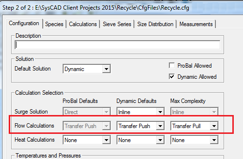
- In the Configuration file, on the 'Configuration' tab, set the Max Complexity for Flow Calculations to Transfer Pull and the Dynamic Defaults to Transfer Push.
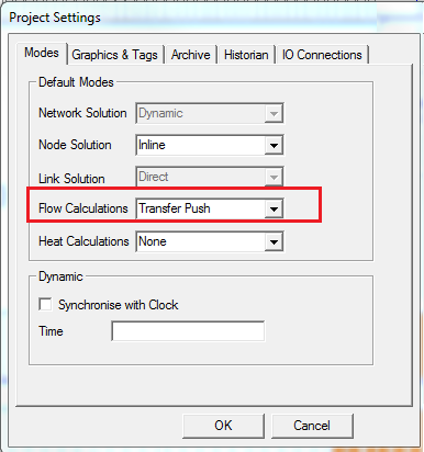
- In the Project Settings, set the Flow Calculations to Transfer Push. Access Project settings either:
- With the Project closed: Edit - Project Settings; or
- With the Project open: Project - Settings.

