Default Graphics for Insert Link
Jump to navigation
Jump to search
Navigation: User Guide ➔ Menu Commands ➔ Graphics ➔ Insert ➔ Default Graphics for Insert Link
Related Links: Insert Link, Graphics Drawing Grids
Introduction
When a user connects 2 units with an Insert Link command, SysCAD will normally construct a default graphics line on the flowsheet. The user may set a number of options to change how SysCAD draws this default link. These options will be explained in the topics below.
Video Link
This video in the Tutorial section: Insert Links to connect Units in a Flowsheet explains the Insert Link process.
Default Drawing Options
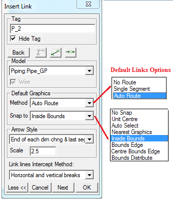
The expanded Insert Link dialog window shows the Default Drawing Options as shown below:
Notes:
- These options may also be set in Tools - General Options - Drawing Tab.
- For a description of the options available for the Link Arrows, please see Link Arrow Options.
- For a description of the options available for the Link Intercept Methods, please see Link Intercept Methods.
Insert Link Default Graphics Method
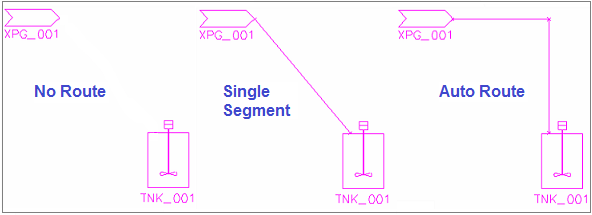
- No Route - SysCAD will NOT construct a Default line when a link is inserted - the user must manually add the line, as described in Graphics for Insert Link and Redraw Link.
- Single Segment - one single line will be drawn between the two points.
- Auto Route - This is the Recommended method. SysCAD will create a line with one or more segments between the Source and Destination units.
Insert Link Default Graphics Snap To Options
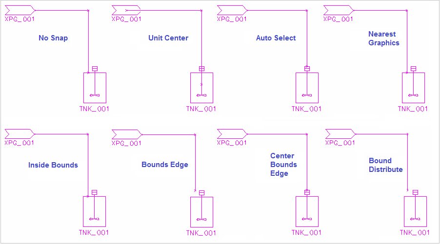
- No Snap - just use the digitized points. (The points selected when clicking on source and destination units are ignored.)
- Unit Center - between the two centers. (The points selected when clicking on source and destination units are ignored.)
- Auto Select - goes between the two closest bounding box edges. (The points selected when clicking on source and destination units are ignored.) This is used in Graphics Copy and Paste when the link is a non-standard link, and is also used in COM Automation for default links.
- Nearest Graphics - Snap to the nearest point on the graphic
- Inside Bounds - doesn't snap at all if you are inside the bounding box, and snaps to the bounding box edge if you are outside.
- Bounds Edge - Snap to the nearest point on the bounding box
- Centre Bounds Edge - Snap to the nearest point on the bounding box in the normal direction, and the centre in the transverse direction.
- Bounds Distribute - allows you to space the connection point equally along the edge. Currently the side is divided into six equal segments (so that there are five points along the edge that can be snapped to. For three points on the edge you can snap to the mid point, 25% and 75%.
- The above Examples were drawn using the Auto Route Default Graphics Method.
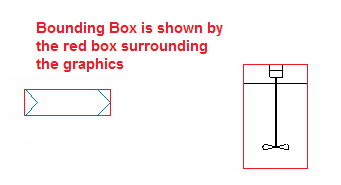
- The bounding box is a rectangle around the Unit Operation Graphics, fitting all the graphical lines within. This means not all the graphical lines will be on the edge of this bounding box.


