Explorer Window
Navigation: User Guide ➔ Windows ➔ Explorer Window
| Application Window | Message Window | Graphics Window | Access Window | Explorer Window | Trend Window | Controls Window | TagList Window | Project Window |
|---|
Latest SysCAD Version: 13 May 2026 - SysCAD Build 139.37082
Introduction
The SysCAD Explorer Window may be accessed in any of the following ways:
| Command Button | |||
| Command Path | View - Explorer | OR | Window - Select Window |
| Short Cut Key | Ctrl+E | OR | Ctrl+W |
The Explorer window can be used to:
- navigate the documents and windows in the project.
- access shortcuts to some features and settings through right-click context menus.
- arrange the Graphics pages into Areas.
- view all the unit models in the project. This can be by Graphics or by other lists such as by UnitTypes.
- find model
The Explorer window is not necessarily constrained within the boundaries of the SysCAD window and may be moved beyond the SysCAD limits depending on the settings in General Options. This is a useful feature for managing screen space to view the actual project.
The layout of the Explorer Window is as follows:
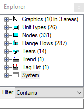
- Graphics (The total number of Graphics Windows and Areas in the project will be shown here)
- open this outline level will show all the areas in the project
- open this outline level will show all the graphics windows in the project
- then next level will show all the unit operations on the selected graphics windows
- open this outline level will show all the graphics windows in the project
- open this outline level will show all the areas in the project
- UnitTypes (The total number of UnitTypes in the project will be shown here, can be turned off by right clicking and select Hide UnitTypes)
- open this outline will show all the unit types in the project
- next level will show all the units for the selected unit type
- Nodes (The total number of Nodes in the project will be shown here, can be turned off by right clicking and select Hide Nodes)
- open this outline will show all the unit operations in the project in one long list
- Flange Flows Available from Build 139.31388. (The total number of Flanges in the project will be shown here, can be turned off by right clicking and select Hide Flange Flows)
- open this outline will show the three types of flanges, Flange, Flange-In and Flange-Out.
- open this outline will show all the flanges of the chosen type.
- open this outline will show the three types of flanges, Flange, Flange-In and Flange-Out.
- Tears (The total number of Tears blocks in the project will be shown here, can be turned off by right clicking and select Hide Tears)
- open this outline will show all the tear blocks in the project in one long list
- Trend (The total number of Trend Windows in the project will be shown here)
- open this outline level will show all the Trend windows in the project
- Tag List (The total number of TagList Windows in the project will be shown here)
- open this outline level will show all the TagList windows in the project
- System
- open this outline level will show the two Access Windows, Message Window and Project Window.
- Graphics (The total number of Graphics Windows and Areas in the project will be shown here)

The user may navigate to any Graphics or document window in the project by simply clicking on the required window in the Explorer window. SysCAD will activate the required window.
Flowsheets grouped in Areas
The Explorer Window is very useful when navigating a large project with multiple flowsheets, models and document windows. For flowsheets the user may group these into Areas directly from the Explorer window or in Plant Model Flowsheets tab.
The image below shows the same project with 12 flowsheets. The left window has all of the flowsheets in a single default Area, while the window on the right has flowsheets group by area:

- The Graphics windows are listed alphabetically in the Explorer window, it is often a good idea to number the flowsheets so that they follow the process flow, (shown by left image above)
- If the user has added Areas to the project, then the flowsheets may be grouped by area. This is a really useful feature for a large project that contains many Graphics windows.
- If the user has added Areas to the project, these will also be listed alphabetically, so again it is recommended that the areas are alphanumeric and follow the flow of the project, (shown by right image above)
Notes:
- Flowsheets can be dragged and dropped into areas using the Explorer Window.
- The Explorer default behaviour can be found on Tools | General Options | General.
- Graphics, Trend and TagList information are always available;
- Nodes, Tears and Flows (Flows are only available for dynamic projects) information will be Off by default. The user may right click on the group and choose Show.
Document Type Right Click Options
Graphics
The Graphics Options have four levels: Overall Graphics, Area, Individual Flowsheets and Individual Units.
Flowsheets can be dragged and dropped between Areas. And Areas can be managed through right click context menus for the Explorer window Graphics as described below.
Overall Graphics
|
Right click on Graphics in the Explorer window for the pop up menu as shown:
This allows the user to carry out a number of actions:
|
Area
|
Right click on an Area name in the Explorer window for the pop up menu as shown: This allows the user to carry out a number of actions:
|
Individual Flowsheets
|
Right click on a Flowsheet name in the Explorer window for the pop up menu as shown:
This allows the user to carry out a number of actions on the flowsheet:
|
Individual Units
|
Right click on a Unit name in the Explorer window for the pop up menu as shown:
This allows the user to carry out a number of actions on the flowsheet:
|


Unit Type
The Unit Type Options have three levels: Overall UnitType, Individual UnitType and Individual Units.
Overall UnitType
|
Right click on UnitType in the Explorer window for the pop up menu as shown:
This allows the user to carry out a number of actions:
|
Individual UnitType
|
Right click on a Unit Type name in the Explorer window for the pop up menu as shown:
This allows the user to carry out a number of actions on the flowsheet:
|
| Individual Units | As per Graphics - Individual Unit |


Other Document Types
Trend |

|
Right Click on the Trend (overall) has the following options:
Right click on an individual Trend has the following options:
|
|---|---|---|
TagList |

|
Right Click on the TagList (overall) has the following options:
Right click on an individual TagList has the following options:
|
Others
Nodes is a simple list of all models. Flange Flows is a list of all flanges (the connection flange objects between pipes and models). Tears is a list of all Solver Tears.
Nodes |

|
Right click on Nodes (overall) in the Explorer window has the following options:
Right Click on an individual Node is as per Graphics - Individual Unit |
|---|---|---|
Flange Flows |

|
Available from Build 139.31388.
Right click on Flange Flows (overall) in the Explorer window has the following options:
Right Click on Flange (between cross-page connectors), Flange-In (between pipe and unit) or Flange-Out (between unit and pipe) has the following option:
Right Click on an individual Flange has the following options:
|
Tears |

|
Right click on Tears (overall) in the Explorer window has the following options:
|
Creating Equipment or Pipe List
User can get full equipment list from the Explorer window by :
- right clicking on Graphics - data copied may include Area (if used), Graphics page and/or Unit Tag names. (Sorted by Area, Graphics then by Unit Tag Name)
- Right clicking on Unit Types - data copied may include unit type and / Unit Tag names. (sorted by unit type, followed by Unit Tag name)
- Right Clicking on Nodes (if shown) - data copied is Unit Tag names (sorted)


User can also selectively copy some equipment that meets some criteria, by using Filter. This is explained in the next heading.
Pipe List for a Graphics Page
The user may limit the units that are displayed by using the Filter at the bottom of the Explorer Window.
For example, if the user wishes to copy the pipes on a single graphics page, and the pipes all have the naming convention P_xxx, then in the filter window
- choose Filter type "Contains" or "StartsWith" then
- type in P_ as shown in the picture below.
|
|
Tag P_001 P_002 P_004 P_005 P_006 P_007 P_003 |

Missing Models or Graphics
Models Marked with Red Cross
Missing models will be marked with red cross.
- A Missing Model refers to a SysCAD unit model that's been deleted, but the Graphics still exist.
- This could be a result from the following actions:
- A SysCAD unit model/graphics page has been deleted
- User closes graphics page without saving
- User then saves the project. (Closed graphics page will NOT be saved)
- User then closes and opens the project, and reopens the graphics page (that was not saved).
- As a result, the model has been deleted from the database but the graphics file has not been updated, thus causing the mismatch.
- The easiest way to check for missing models is by looking at the Graphics page directly (not from Explorer). If miss model exists, the models would appear grey and there is no access window when you click on them.
- The recommended action for Missing Model with graphics is to delete all the dummy graphics using Graphics - Delete, then re-build the flowsheet.
Missing Graphics
It is possible to get into a situation where "orphan" models without Graphics Representation exist in the SysCAD project.
The missing Graphics could be due to user accidentally closing the Graphics Page, or Graphics Symbol got "corrupted" and has gone missing, thus creating "orphan" models without graphics representation.
- If the models are valid and must exist, then the graphic symbols should be added back to the project.
- In the case of missing an entire page: try and located the missing graphic page from previously saved versions, copy back into the project and open it using Open file: "xxxx.scg"
- In the case of missing single Graphics Symbol:
- In the empty spaces where the graphics should be, use Graphics-Insert Symbol to add back an appropriate Graphics Symbol. (This is a dummy symbol)
- Use Graphics - Construct Symbol to attached this dummy symbol to an orphan model. (See also Manipulating Graphics)
- If the Orphan models in the project are NOT required, then user can delete these orphan models using the Explorer Window:
- From the section called Missing Graphics under the graphics tree, open that tree to get a list of all the unit operations in the project without graphics.
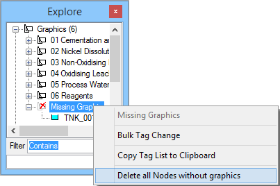
- If user wish to delete all the orphan models, simply right click on the word Missing Graphics to bring up a popup menu, select the option to Delete all nodes without graphics.
- From the section called Missing Graphics under the graphics tree, open that tree to get a list of all the unit operations in the project without graphics.
- Once that is done, save the project, close and reopen Explorer to refresh the explorer list. User should find that the missing graphics is fixed.
